


Hardware User Manual
3onedata proprietary and confidential 15
Copyright © 3onedata Co., Ltd.
Pin Name
Pin No.
Type
Function Description
U0_TXD
C33
Output
UART0 Transmitted signal, used for
CONSOLE port to debug this module
only.
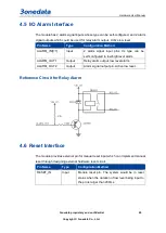
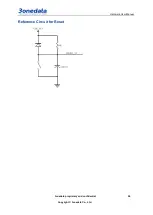
3.4.6 I/O Alarm Interface
The description of I/O alarm interface pin definition:
Pin Name
Pin No.
Type
Function Description
ALARM_OUT2 C6
Output The pin of 2-way alarm signal output. It
corresponds to the status of 2-way alarm
signal input. When the status of any one
input changes, so do the two outputs.
ALARM_OUT1 could be extended to
relay. Active low level.
ALARM_OUT2 could be extended to
alarm indicator. Active low level.
ALARM_OUT1 C11
ALARM_IN0
C16
Input
The pin of 2-way alarm signal input. It
could configure alarm input type on its
own, such as power alarm information
detection. Active-high level range is
2.7~3.5VDC.
ALARM_IN1
C15
3.4.7 Indicator
The description of indicator pin definition:
Pin Name
Pin No. Type
Function Description
CPU_RUN
C12
Output The pin of running indication signal output.
CAN1_ERR
C44
Output CAN1 error indicator, Active low level.
CAN2_ERR
C43
Output CAN2 error indicator, Active low level.
LINK1
B14
Output
100M Ethernet port connection and data
transmission indication pin LINK[1:5].
When the pin LINK[1:5] outputs high
levels, it means the corresponding 100M
LINK2
B18
LINK3
B22
LINK4
B26


