


Hardware User Manual
3onedata proprietary and confidential 13
Copyright © 3onedata Co., Ltd.
3.4.2 Power Supply and Ground Signal
Pin definition description of power supply and ground signal:
Pin Name Pin No.
Type
Functional Description
VIN_3V3
A41, A42, A43
Input
3.3VDC voltage input, it provides
power supply for the module.
OUT_2V5 A47, A48
Output 2.5VDC voltage output, it's used for the
centre tap of the Ethernet port network
transformer and can't be used for other
purposes.
GND
A1, A2, A5, A6,
A9, A10, A13,
A14, A17, A18,
A21, A22, A25,
A26, A29, A30,
A33, A34, A37,
A38, A44, A45,
A49, A50, B1 B2,
B4, B8, B11,
B12, B15, B19,
B23, B27, B31,
C1, C2, C3, C4,
C27, C28, C29,
C30, C37, C38
Ground
Ground signal
3.4.3 TTL UART Interface
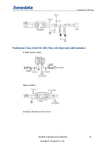
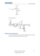
The TTL UART could be extended to RS-232/RS-485/RS-422 serial port.
The description of 2-way TTL UART pin definition:
Pin Name
Pin No. Type
Function Description
UART1_RX
C36
Input
UART1 Received signal
UART1_TX
C35
Output
UART1 Transmitted signal
UART1_RTS C31
Output
UART1 Request to Send signal
Note:
When UART1 is extended to RS-485/422 serial


