background image

3M™ MicroTouch™ Controller RX182 Reference Guide 

11 


3M Touch Systems, Inc. Proprietary Information 

PC Side  (9-Pin D) 

Controller Side (8-Pin Molex) 

Pin 

RS-232 Assigned 

Jumpered to: 

Pin Description 

Data Set Ready (DSR) 

1 and 4 DCD and DSR  8 

DCD, DTR, DSR 

Request to Send (RTS) 


Request to Send (RTS) 

Clear to Send (CTS) 


Clear to Send (CTS) 

Not Used 


Do not ground 

Sleeve   


DC power jack (+5 VDC) 

Pin 


Cable shield connected to 
ground. DC power jack 
ground 

Shell 


Chassis (earth) ground 

Mounting the Controller 

The controller is designed for internal mounting only. Choose a convenient spot away 
from high-voltage, high power cables and electronics. Use 4-40 metal screws to mount 
the controller using the two diagonal mounting holes in the board. The controller should 
be mounted in line with the sensor cable exit point to minimize cable flexing. The 
controller should be mounted internally behind or on the side of the display on stand offs 
to allow room for the sensor cable connector. 

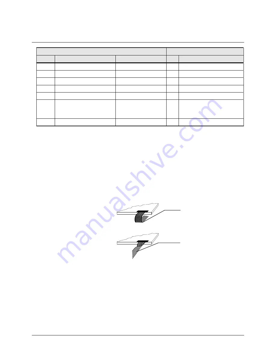
Ensure that the tail and controller are aligned such that the tail remains straight (90

°

), not 

pulled or twisted in an odd angle from the sensor. Good engineering design avoids 
awkward electrical connections. 


Supplying Power to the Controller 

You must supply the RX182 controller with power. The source must deliver (for 5 VDC) 
16 mA typical, 27 mA touching; 

±

 5% regulation or (for 12 VDC) 19 mA typical, 30 mA 

touching; 

±

 5% regulation, with a maximum ripple and noise of 50 mV peak-to-peak.  

You can supply power to the RX182 controller using any of the following methods. The 
voltage input can be 5VDC or +12VDC. In Sleep Mode the controller draws less 
than 5 mA.  
 

Not recommended: 
Do not twist the tail  

Recommended: 
Wrap tail smoothly  

Содержание Touch Screen Controller RX182

Страница 1: ...stems Inc Proprietary Information 3M MicroTouch Controller RX182 Reference Guide Formerly SC800 Serial Resistive Read and understand all safety information contained in this document before using this...

Страница 2: ...ot warranted 3M Touch Systems Inc products and software are not specifically designed for use in medical devices as defined by United States federal law 3M Touch Systems Inc products and software shou...

Страница 3: ...stablishing the Data Connection 10 Mounting the Controller 11 Supplying Power to the Controller 11 Mounting the Sensor 12 Sensor Cable Connector 12 Status Light LED Diagnostics 13 Turning On Your Syst...

Страница 4: ...uch Systems Inc Proprietary Information Restore Defaults 24 Set Controller Number Error Bookmark not defined Unit Type 24 Appendix A RX182 Controller Specifications Technical Specifications 28 Storage...

Страница 5: ...ted to being a premier supplier in touch systems throughout the world As a 3M Touch Systems customer you are aware that we have strong internal programs that meet or exceed environmental regulations o...

Страница 6: ...ury or death Do not use a damaged power supply Do not use a power cord that is frayed or otherwise damaged CAUTION To reduce the risks associated with improper disposal which if not avoided may result...

Страница 7: ...through Friday 8 30 a m to 5 30 p m with limited call back service after 5 30 p m until 8 00 p m US Eastern Standard Time 9 a m to 5 p m throughout Europe You can contact 3M Touch Systems Technical Su...

Страница 8: ......

Страница 9: ...nd 1 stop bit To integrate and test the RX182 controller you need the following items A 8 wire resistive sensor A method of establishing the serial data communication between the controller and your s...

Страница 10: ...or JP2 You can use a standard 3M MicroTouch RS 232 plug and play cable P N 7319630 or an equivalent interconnect One end of this cable plugs into the RS 232 connector JP2 on the RX182 controller The o...

Страница 11: ...should be mounted in line with the sensor cable exit point to minimize cable flexing The controller should be mounted internally behind or on the side of the display on stand offs to allow room for th...

Страница 12: ...lex connector Refer to Table 1 for more information on actual cable connections Unlike using JP4 to supply power you can only use 5VDC at the serial interface 1 Obtain an 8 pin Molex connector 51004 0...

Страница 13: ...sensor the LED becomes bright as long as the controller detects a touch A flashing or blinking LED during power up indicates the controller s power on self test failed Refer to the following table fo...

Страница 14: ...or many operating systems including Windows Vista XP XP embedded 2000 9X Windows Me Windows CE and Windows NT 4 0 refer to the website for a complete listing You must be sure to install the correct so...

Страница 15: ...d includes the command syntax the default value how the command works and the expected response from the controller Controller Default Settings Communication Parameters The RX182 controller communicat...

Страница 16: ...ed in the following table are those that 3M Touch Systems currently uses for development and recommends that you use only these commands Commands to the controller are sent on the signal Receive Data...

Страница 17: ...ontrol character is 01 If you are working with an IBM PC compatible system in terminal mode the SOH control character returns a character to the sensor The response which always follows the header is...

Страница 18: ...tialize the controller select operating modes specify data formats and execute diagnostic functions Most touch system users do not have to use firmware commands to use their touch systems For example...

Страница 19: ...Number W002 Used to determine a controller ID number for multiple monitor applications Unit Type UT Returns controller unit type string and status Calibrate 3 Point Syntax SOH C3 CR Response SOH 0 CR...

Страница 20: ...o register a calibration touch Therefore you can touch the coordinate target hold for a few seconds and then lift off Instructing users to touch this way results in a more accurate calibration The con...

Страница 21: ...n the following format SXxYy S Status byte first byte of data Refer to Table 4 Xx X horizontal coordinate data second and third bytes of data Yy Y vertical coordinate data fourth and fifth bytes of da...

Страница 22: ...ty bit changes from 1 to 0 touch liftoff the controller outputs one final set of X Y coordinate data with the bit equal to 0 and the X Y coordinate data equal to the last touch point S7 Packet synchro...

Страница 23: ...Returns a 6 character identifier which describes the controller type and the firmware version number The output identity for the RX182 controller is SCXxxx Reset Syntax SOH R CR Response SOH 0 CR Posi...

Страница 24: ...Tablet Operating Mode Mode Stream Return to Factory Calibration Yes Note After you issue a Restore Defaults command you must recalibrate your sensor Set Controller Number a multi step command Syntax...

Страница 25: ...her 4 wire controller RX142 or an 8 wire controller RX182 Indicates no additional features configured Ss Two ASCII characters that provide status information about the controller hardware The two char...

Страница 26: ......

Страница 27: ...pecifications such as power requirements environmental requirements and cable connectors The RX182 controller is a compact RS 232 serial controller This controller was designed to be mounted inside yo...

Страница 28: ...ZS 3548 1995 CISPR 22 Class B ITE Emissions Aus Class B Compliant RFI EN 61000 4 3 ENV 50140 Class A Compliant CRFI EN 61000 4 6 N A Cable 3 meters long N A EFT Burst Immunity EN 61000 4 4 Class B Com...

Страница 29: ...on 9 of IEC 61000 4 2 Compliant 1 false touch allowed 20 kV Air Discharge Class 1 per section 9 of IEC 61000 4 2 Compliant Normal Operation No false touches ESD discharges to a sensor connected to the...

Отзывы: