3M
™
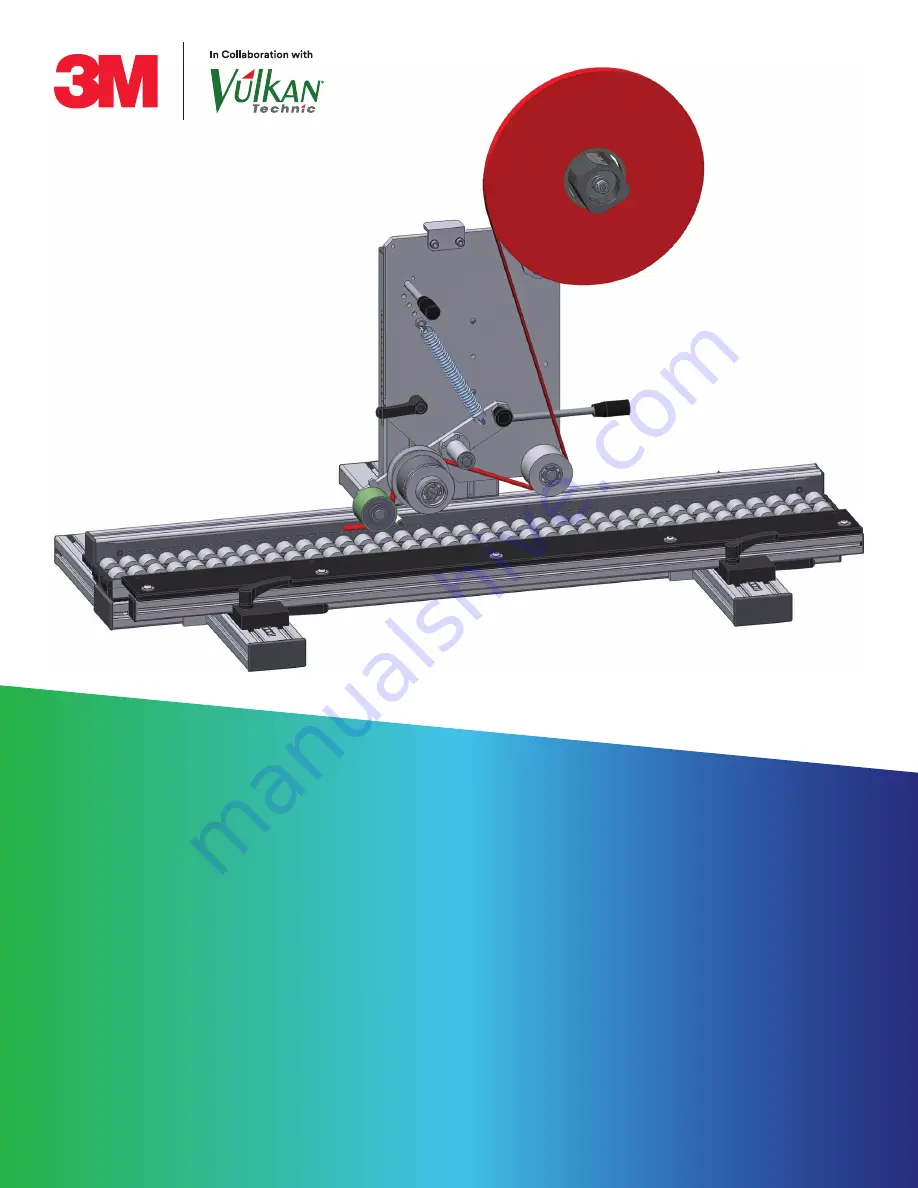
Straight Line
Laminator Single Head
Manual
Effective: August 2022
Original Assembly and Operation Instructions
Страница 1: ...3M Straight Line Laminator Single Head Manual Effective August 2022 Original Assembly and Operation Instructions ...
Страница 2: ...ite of Operation 8 2 6 Mandatory Signs Used 9 2 7 Personal Protective Equipment 9 2 8 Warning Signs Used 10 2 9 Warning Notices 10 2 10 General Safety Information 10 3 0 Safety Devices 11 3 1 Type Plate 11 3 1 1 General Information 11 3 1 2 Type Plate Continuous Laminator 11 4 0 Design and Functions 11 4 1 Technical Data 11 4 2 Overview Design and Functions 12 4 3 Workplaces 12 4 3 1 Workplace Pro...
Страница 3: ...g Diagram SGA 500 L 32 7 0 Assembly Installation 33 8 0 Errors Malfunctions 33 9 0 Service and Maintenance 34 9 1 Maintenance and Replacement 34 9 1 1 Maintenance and Replacement of the Deflection Pulley 34 9 1 2 Maintenance and Replacement of the Adjustable Deflection Pulley 35 9 1 3 Maintenance and Replacement of the Downholder 35 9 1 4 Maintenance and Replacement of the Application Roller 36 9 ...
Страница 4: ...spective relevant document in the corresponding sections For supplementary documents to these instructions such as assembly drawings and parts lists the following notes apply All plans and drawings are for information only and are not subject to updating The disclosure the reproduction of these drawings and or plans as well as utilization and notification to third parties are not permitted without...
Страница 5: ...ame Example For further information please refer to the manufacturer documentation Button or switch designations are set in quotation marks Example Press illuminated button System On Designations from a digital user interface are marked with the following character formatting Example Press button System On 1 3 3 Handling Instruction If the operating instructions consist of several operating steps ...
Страница 6: ...aw 3M will not be liable for any loss or damage arising from or related to the 3M product whether direct indirect special incidental or consequential including but not limited to lost profits or business opportunity regardless of the legal or equitable theory asserted including but not limited to warranty contract negligence or strict liability Disclaimer 3M industrial and occupational products ar...
Страница 7: ...ve task and have been briefed on the special conditions at the system s location Clearly regulate and specify the responsibilities of the staff for installation operation maintenance and cleaning Regulate the responsibility for the operation of the system and allow the staff to refuse instructions from third parties that impair safety Ensure that all employees have read and understood the parts of...
Страница 8: ...or damage caused by unintended use Other prerequisites for intended use are Compliance with all valid operating instructions of the operator Compliance with the instructions in this documentation The regular performance of repair work as stipulated in this manual and in the manufacturer documentation 2 3 Improper Use Any use of the system exceeding the use described in chapter 2 4 Intended Use Thi...
Страница 9: ...ntenance work 3M cannot provide any warranty in relation to the readability of the CD for the storage period required Please archive a printed copy of the operating instruction 2 7 Personal Protective Equipment When performing maintenance personal protective equipment must be worn in order to minimize hazards Signs placed in the work area regarding personal protective equipment are to be followed ...
Страница 10: ...and to prevent personal injury or material damage The following category of warning notices will be used NOTE Important information for an efficient and undisturbed work flow 2 10 General Safety Information Warning notices are particularly highlighted in this manual compared to the rest of the text The warning notices must be followed strictly in order to ensure accident free work and to prevent p...
Страница 11: ...ype Plate Continuous Laminator The type plate is located at the front of the base plate The registered serial number can be found on the attached type plate Figure 1 4 0 Design and Functions 4 1 Technical Data Dimensions L x W x H approx in the standard setting and without adhesive tape roll 385mm x 512mm x 240mm 385mm x 512mm x 266mm 385mm x 512mm x 290mm Dimensions L x W x H approx 1008mm x 596m...
Страница 12: ...August 2022 4 2 Overview Design and Functions Figure 2 Figure 3 4 3 Workplaces 4 3 1 Workplace Production Figure 4 A Continuous Laminator SGA 500 R Tape Version 05 30 30 55 10 50 55 80 B Continuous Laminator SGA 500 L Tape Version 05 30 30 55 10 50 55 80 C Product Guide Version SGA 500 Workplace operator C A B ...
Страница 13: ...e the adhesive tape roll in the system please see chapter 6 8 Threading Diagram SGA 500 R and chapter 6 9 Threading Diagram SGA 500 L 4 4 Function The manual workplace here the Continuous Laminator SGA500 is used for the application of single sided or double sided adhesive tape to different product surfaces Workplace operator Workplace for the change of the adhesive tape roll ...
Страница 14: ...duct The compression spring holds the application roller down and thus ensures the necessary contact pressure of the adhesive tape on the product surface 4 Push a second product on the roller conveyor and pass both of them under the application roller As soon as the first product is a little behind the application roller cut the adhesive tape between the two products NOTE Danger in the area when c...
Страница 15: ...e compression spring holds the application roller down and thus ensures the application of the adhesive tape to the product surface 4 Push a second product on the roller conveyor and pass both of them under the application roller As soon as the first product is a little behind the application roller cut the adhesive tape between the two products NOTE Danger in the area when cutting the tape Danger...
Страница 16: ... plates The attached adhesive labels or plates must not be removed or covered Dirty or damaged adhesive labels or plates must be cleaned or replaced to ensure a perfect recognition If parts of the system are replaced please make sure that the spare parts or replacing parts bear the respective adhesive labels or plates NOTE For the meaning of the hazard and warning labels please refer to the docume...
Страница 17: ...Risk of crushing Watch out for moving parts when threading the tape Optional accessories The application roller is available in a softer version A Tape Mounting 3 B Stop C Base Plate D Handle E Mounting Stand R F Compression Spring G Locking Lever H Application Roller I Downholder J Adjustable Deflection Pulleys K Deflection Pulley L Locking Bolt M Swivel Lever A B C D D E F G H L I M J K ...
Страница 18: ...Risk of crushing Watch out for moving parts when threading the tape Optional accessories The application roller is available in a softer version A Tape Mounting 2 B Stop C Base Plate D Handle E Mounting Stand L F Compression Spring G Locking Lever H Application Roller I Downholder J Adjustable Deflection Pulleys K Deflection Pulley L Locking Bolt M Swivel Lever A B C D D E F G H L I M J K ...
Страница 19: ...Risk of crushing Watch out for moving parts when threading the tape Optional accessories The application roller is available in a softer version A Tape Mounting 3 B Stop C Base Plate D Handle E Mounting Stand R F Compression Spring G Locking Lever H Application Roller I Downholder J Adjustable Deflection Pulleys K Deflection Pulley L Locking Bolt M Swivel Lever A B C D D E F G H I M J K L ...
Страница 20: ...Risk of crushing Watch out for moving parts when threading the tape Optional accessories The application roller is available in a softer version A Tape Mounting 3 B Stop C Base Plate D Handle E Mounting Stand R F Compression Spring G Locking Lever H Application Roller I Downholder J Adjustable Deflection Pulleys K Deflection Pulley L Locking Bolt M Swivel Lever A B C D D E F G H L I M J K ...
Страница 21: ... Rubber Coating 70 Shore Item Designation Item Number 1 Application roller Ø50x40 mm 120766 V 2 Application roller Ø50x60 mm 202958 C 3 Application roller Ø50x80 mm 159990 V Application Roller with PU Coating Item Designation Item Number 1 Application roller Ø50x40 mm 449170 C 2 Application roller Ø50x50 mm 159865 V 3 Application roller Ø50x60 mm 159852 V A Foot Stand B Product Stop at the Top C L...
Страница 22: ...othing and jewelry away from rollers and spring Always position body as instructed per user instructions 6 2 Standard Setting Compression Spring It is generally recommended to carry out the application work with the standard setting Figure 15B second mounting position from below of the compression spring NOTE Excessive pressure during application leads to stretching of the tape and possibly to fau...
Страница 23: ... nut M8 DIN 934 spanner size 13 Figure 15C Mounting position upwards Increasing the spring tension Mounting position downwards Decreasing the spring tension 5 Hook the compression spring with the loosened side back into spring holder Figure 15E The compression spring is newly adjusted 6 3 Installation of the Unit The unit is mounted by the operator on an existing worktable This can be done using t...
Страница 24: ...he product stop and the center of the bonding track 3 Tighten the three bolts Figure 17B M8x20 DIN EN ISO 4762 Allen key size 6 at the back of the mounting bracket The track center is set up Figure 18 4 Hold the base plate of the bonding head firmly using the handle bar Figure 18C and release the locking lever Figure 18B 5 Move the base plate to the desired position using the handle bar Figure 18C...
Страница 25: ...e deflection pulley Figure 19A NOTE To set up the width of the adhesive tape roll in the unit please see chapter 6 5 Setting the Track Width on the Adjustable Deflection Pulley Figure 20 9 Put the adhesive tape roll on the tape mounting Figure 20A and adjust the tape brake if necessary NOTE To set up the tape brake in the unit please see chapter 6 7 Setting the Tape Brake A A ...
Страница 26: ...ng diagram Figure 22 11 Adjust the guide rail Figure 22A for the lower product stop To do so loosen the two locking levers 22B on the product guide and move the guide rail to the desired position The attached scale Figure 22C serves as an adjustment aid for the width of the product 12 Tighten the two locking levers Figure 22B again The product is set up The continuous laminator is ready B C A ...
Страница 27: ...e width There is a separate deflection pulley Figure 23 for each SGA size but they are set up identically Figure 23 Type Information SGA 500 R 05 30mm SGA 500 L 05 30mm SGA 500 R 30 55mm SGA 500 R 55 80mm Figure 24 1 Remove the adhesive tape roll from the tape mounting and the adhesive tape from the rollers Figure 24A 2 Loosen the locking washer at the adjustable deflection pulley Figure 24B and t...
Страница 28: ... the adjusting sleeve clockwise to decrease the track width on the adjustable deflection pulley 4 Adjust the track width to the new tape width Figure 25B To do so turn the adjusting sleeve Figure 25A clockwise to the corresponding track width NOTE Make sure that the adhesive tape can move properly in the new track Figure 26 5 Turn the locking washer Figure 26B clockwise against the adjusting sleev...
Страница 29: ...counter holding there is a slot on the other side of the threaded axle Figure 28F 2 Change the position of the adjustable deflection pulley Figure 28B by screwing the threaded axle out or in 3 Tighten the lock nut M16x1 DIN 439 spanner size 24 Figure 28A again The adjustable deflection pulley is now positioned to the new bonding track 4 Loosen the lock nut M18x1 spanner size 27 Figure 28C at the t...
Страница 30: ...d evenly in the work process the tape brake of the tape mounting must be adjusted Make sure that the tape is not subjected to strong tension Figure 30 1 Use an Allen key size 5 at the axle mount Figure 30B to fix it 2 Use an open end spanner size 17 to turn the nut Figure 30B on the axle mount A Turning clockwise the spring is tensioned further the force of the tape brake increases B Turning count...
Страница 31: ...Page 31 3M Straight Line Laminator Single Head Manual Original Assembly and Operation Instructions Effective August 2022 6 8 Threading Diagram SGA 500 R Figure 31 ...
Страница 32: ...Page 32 3M Straight Line Laminator Single Head Manual Original Assembly and Operation Instructions Effective August 2022 6 9 Threading Diagram SGA 500 L Figure 32 ...
Страница 33: ...or Possible Cause of Error Remedy Adhesive tape not clean Soiling on the rollers the downholder Clean rollers and downholder Adhesive tape does not stick to the product Adhesive tape tears Tape brake set too strong Change the setting of the tape brake See chapter 6 7 Setting the Tape Brake Bonding track not correct Track course is wrong Track position not correctly set Check the track position and...
Страница 34: ...e to check for worn parts and replace if necessary The application roller the downholder and the two deflection pulleys must be cleaned regularly If the parts contribute more quickly to an insufficient production quality the corresponding rollers or the downholder can also be cleaned daily if necessary In case of major wear it may be necessary to replace the rollers the two deflection rollers and ...
Страница 35: ...n reverse order 9 1 3 Maintenance and Replacement of the Downholder Figure 35 1 To work on the downholder first remove the application roller see chapter 10 1 4 Maintenance and Replacement of the Application Toller 2 To replace the downholder Figure 35A remove the retaining ring Figure 35D 3 Now you can pull the bearing sleeve Figure 35C off the downholder axle Figure 35B 4 Assembly takes place in...
Страница 36: ...ontinuous Laminator As required Over time residues of the adhesive tape may deposit In case of increased wear it may be necessary to replace highly stressed components Non stick Coated Parts Monthly immediately when adhesive tape begins to stick Check for damages and non stick effect and replace if necessary 9 3 Cleaning Schedule Assembly Group Interval Work to be Performed Continuous Laminator Ev...
Страница 37: ... with compliance with EU or respective national legislation on environmental protection at the time of decommissioning The locally applicable laws rules and regulations and the safety instructions in this manual are to be complied with When handling utilities and auxiliaries follow the safety instructions applicable to the respective product Follow the safety data sheets for the utilities and auxi...
Страница 38: ... Recycle plastic elements Dispose of leftover components sorted by their material composition The local municipal authority or specialized waste management companies provide information on environmentally sound disposal 12 2 Packaging Environmentally sound disposal preserves the environment and allows a sustainable and efficient handling of resources Comply with national and local regulations conc...
Страница 39: ...ble locking lever GN 604 pdf Data sheet Cylinder heads GN 519 2 pdf Glacier ggb datasheet ggb bp25 sintered bronze plain bearing pdf Misumi Data sheet Spring anchors SAIPO8 20 pdf Data sheet Rollers pdf Norelem 08910_A_Datasheet_4371_ drill bushes with collar _DIN_172_Shape_A de pdf The purchase parts documentation will only be supplied in digital form with the enclosed data medium 14 0 Manufactur...
Страница 40: ...ive August 2022 Industrial Adhesives and Tapes Division 3M Center Building 225 3S 06 St Paul MN 55144 USA Phone 1 800 362 3550 Web 3M com VHB 3M is a trademark of 3M Used under license in Canada All other trademarks are property of their respective owners Please recycle 3M 2022 All rights reserved ...