


© 3M 2006
15
Repair Procedures
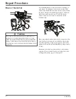
Follow “Handle Disassembly Instructions,” Procedure
A on page 13. The power cord wire from the switch is
removed from the bayonet connector. The black and
white wires are removed from their respective
terminals. Remember which wire came off which
terminal for reassembly. Consult the electrical wiring
arrangement on page 21. Reassemble, following
reverse procedure.
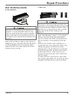
F. Switch Kit
E. Power Cord Kit
Caution
Disconnect air and electrical power and make sure
applicator is at room temperature before servicing
3M™ Scotch-Weld™ Hot Melt Applicator PG II LT.
Failure to disconnect air and electrical power before
servicing may cause electrical shock or damage to the
applicator.
!
Caution
Disconnect air and electrical power and make sure
applicator is at room temperature before servicing 3M
Scotch-Weld Hot Melt Applicator PG II LT. Failure to
disconnect air and electrical power before servicing
may cause electrical shock or damage to the
applicator.
!
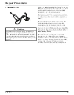
Follow “Handle Disassembly Instructions,” Procedure
A on page 13. Lift the switch from the slot in the right
half of the handle. The power lead can be unplugged
from the power cord receptacle. The other wires
terminating in ring lugs should be removed from their
respective terminals, noting that the black lead is
connected to the Thermal Cut Out Assembly and the
white lead to the heaters. Install the new switch using
reverse procedure.
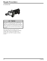
G. Trigger Kit
Follow “Handle Disassembly Procedures,” Procedure A
on page 13. Lift the trigger assembly off the trigger pin
and replace. Reassemble, following reverse procedure.
Caution
Disconnect air and electrical power and make sure
applicator is at room temperature before servicing 3M
Scotch-Weld Hot Melt Applicator PG II LT. Failure to
disconnect air and electrical power before servicing
may cause electrical shock or damage to the
applicator.
!