background image

(A)

(B)

(C)

(D) 

(E) 

(F) 

(G) 

(H)                    (I)

PARTS AND MATERIALS: 

(included)

•   Where a booster pump is installed on a water 

system, you MUST maintain and inspect the 
attached pressure switch regularly in accordance 
with the booster pump manufacturer’s 
instructions. Contact a plumbing professional 
if you are uncertain how to maintain your booster 
pump system.

•   Where a booster pump is installed on a water 

system, you MUST install an appropriate 
pressure relief valve.  Pressure relief valve must 
be maintained and inspected every 6 months. 
Contact a plumbing professional if you are 
uncertain how select/install/maintain a pressure 
relief valve.

•  Where a booster pump is installed on a water 
    system, you MUST install an appropriate pressure 
    regulating valve and regulate water pressure to 
    <80psi. Contact a plumbing professional if you 
    are  uncertain how select/ install/maintain a 
    pressure regulating valve.
•  DO NOT install in direct sunlight or outdoors.
•  DO NOT install near water pipes which will be in 
    path of a drilling tool when selecting the position to 
    mount the bracket.

•  Mount fi lter in such a position as to prevent it from 
    being struck by other items used in the area of 
    installation.
•  Ensure that the location and fasteners will support 
    the weight of the system when installed and full 
    of water.
•   Ensure all tubing and fi ttings are secure and free 
    of leaks.
•  DO NOT install unit if collet is missing. Contact 3M 
    if collets are missing from any fi ttings.
•  Use compatible fl exible tubing with “push-in 
    connections” (such as PEX tubing, PE tubing, 
    PP tubing)
•  DO NOT install with rigid piping (such as copper,
  aluminum, stainless steel, chrome plated, or
 anodized 

tubing).

To reduce the risk of water leakage or fl ooding, and to ensure optimal
fi lter performance:

•  Change the disposable fi lter cartridge every six months or sooner if you observe a noticeable

reduction in water fl ow rate.

IMPORTANT NOTES

•   Failure to follow instructions will void warranty.
•   Allow a minimum of 2 1/2" clear space under fi lter to facilitate cartridge change.
•   Install with the inlet and outlet ports as labeled. Make sure not to reverse connections.

3

Filter (3US-AF01 or 3US-PF01) (A)
Filter head assembly bracket (B)
2 – 3/8" blue tubing (C)
3/8" male water supply line adapter (D)
3/8" compression hex nut (E)
3/8" ferrule (F)
3/8" tube insert (G)
2 – #2 mounting screws (H)
Time Strip (I)

NOTE: White tube on fi lter head assembly bracket (B) is a pressure relief outlet. Water will NOT fl ow out of this tube.

Содержание 3US-MAX-S01

Страница 1: ...r the reduction of claims specified on the Performance Data Sheet 3US MAX S01 System tested and Certified by NSF International against NSF ANSI Standard 42 and 53 for the reduction of claims specified on the Performance Data Sheet 3US AS01 System tested and Certified by NSF International against NSF ANSI Standard 42 for the reduction of claims specified on the Performance Data Sheet This is a chemical ...

Страница 2: ... the system To reduce the risk associated with hazardous voltage due to an installer drilling through existing electric wiring or water pipes in the area of installation DO NOT install near electric wiring or piping which may be in path of a drilling tool when selecting the postilion to mount the filter bracket NOTICE To reduce the risk associated with property damage due to water leakage or floodin...

Страница 3: ...eing struck by other items used in the area of installation Ensure that the location and fasteners will support the weight of the system when installed and full of water Ensure all tubing and fittings are secure and free of leaks DO NOT install unit if collet is missing Contact 3M if collets are missing from any fittings Use compatible flexible tubing with push in connections such as PEX tubing PE tu...

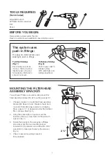
Страница 4: ...ght out 4 MOUNTING THE FILTER HEAD ASSEMBLY BRACKET You will need Phillips screwdriver drill pencil filter head assembly bracket B 2 mounting screws H 1 Choose a location to mount filter head assembly bracket B Keep in mind Bracket should be in a location that offers easy access for changing filters Leave 2 of clearance below the installed filter cartridge See Fig 3 2 Using the bracket B as a guide ma...

Страница 5: ...te If the water supply line adapter D does NOT fit properly onto the end of your faucet hose visit your local hardware store to purchase the correct size Fig 6 Fig 8 Fig 7 5 ATTACH WATER INPUT SUPPLY HOSE You will need 1 length of 3 8 blue tubing C 1 Insert one end of one of the lengths of 3 8 blue tubing C into the push in fitting side of the male water supply line adapter D you just installed Push...

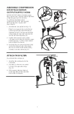
Страница 6: ... tube insert F into the end of the blue tubing C 2 Tighten with a wrench to firmly attach compression kit to the 3 8 cold water supply shutoff valve Fig 11 Pull on blue tubing to assure a tight fit is achieved 3 Push the other end of the same blue tubing C into the left input side of the bracket B Arrows on the bracket will be pointing towards or into the bracket Fig 12 Fig 10 Fig 11 Fig 12 F G E AT...

Страница 7: ...ld water shutoff valve Fig 14 2 Run water to flush 10 gallons 37 85 liters through the system before use Approximately 5 7 minutes 3 Check for leaks If any dripping or leaking occurs turn cold water supply off tighten fittings and assure that tubing is pushed completely into fittings YOUR SYSTEM IS NOW READY FOR USE Fig 14 Water Leaks at Push In Connections Push tubing in as far as it will go If leak...

Страница 8: ...ill replace the Product or refund your Product purchase price This warranty does not cover labor The remedy stated in this paragraph is Customer s sole remedy and 3M s exclusive obligation This warranty gives you specific legal rights and you may have other rights which may vary from state to state or country to country For any warranty questions please call 1 800 388 3458 or mail your request to W...

Страница 9: ... contra las normas 42 y 53 de NSF ANSI para la reducción de reclamos especificados en la Hoja de datos de rendimiento Sistema 3US MAX S01 probado y certificado por NSF International contra las normas 42 y 53 de NSF ANSI para la reducción dereclamos especificados en la Hoja de datos de rendimiento Sistema 3US AS01 probado y certificado por NSF International contra la norma 42 de NSF ANSI para la reducc...

Страница 10: ...sterior al sistema Para reducir el riesgo asociado con voltajes peligrosos que se presenten por taladrar cableado eléctrico o tuberías de agua existentes en el área de la instalación NO instale el producto cerca de cableado eléctrico o de tuberías que pudieran estar en el camino del taladro al seleccionar la posición de montaje del soporte del filtro AVISO Para reducir el riesgo asociado con los da...

Страница 11: ...esión adecuada y regular la presión de agua a 80 psi Comuníquese con un plomero profesional si no está seguro de cómo seleccionar instalar realizar el mantenimiento de la válvula reguladora de presión NO instale bajo luz solar directa ni en exteriores NO instale el producto cerca de tuberías de agua que pudieran estar en el camino de un taladro al seleccionar la posición de montaje del soporte Mon...

Страница 12: ...ORTE DEL MONTAJE DE LA CABEZA DEL FILTRO Necesitará Destornillador Phillips taladro lápiz soporte del montaje de la cabeza del filtro B tornillos de montaje Nº 2 H 1 Elija un lugar para instalar el soporte del montaje de la cabeza del filtro B Tenga presente El soporte debe estar ubicado de manera tal que permita un fácil acceso para el cambio de filtros Deje un espacio libre de 2 debajo del cartucho...

Страница 13: ...o y un lado a presión Fig 8 Nota Si el adaptador de la línea de suministro de agua D NO se conectara apropiadamente al extremo de la manguera de su grifo visite su ferretería local para comprar el tamaño correcto Fig 6 Fig 7 Fig 8 13 ANEXE LA MANGUERA DEL SUMINISTRO DE ENTRADA DEL AGUA Necesitará 1 segmento de tubería azul de 3 8 C 1 Inserte un extremo de uno de los segmentos de la tubería azul de...

Страница 14: ...to de tubo de 3 8 F al extremo de la tubería azul C 2 Ajuste con la llave inglesa para anexar firmemente el kit de compresión a la válvula de cierre de 3 8 del suministro de agua fría Fig 11 Tire de la tubería azul para asegurarse de haber logrado una conexión ajustada 3 Empuje el otro extremo de la misma tubería azul C adentro del lateral izquierdo entrada del soporte B Las flechas del soporte qued...

Страница 15: ...ho hacia abajo para su extracción 3 Alinee las lengüetas del cartucho nuevo del filtro con el soporte de montaje e inserte el cartucho nuevo del filtro en el soporte Fig 15 Gire el cartucho hacia la derecha hasta que se detenga 4 Deje correr el agua hasta que purgue 37 85 litros 10 galones a través del sistema antes de utilizar Aproximadamente de 5 a 7 minutos Fig 14 15 Fugas de Agua en las Conexion...

Страница 16: ...cio de compra del producto Esta garantía no cubre el costo de mano de obra El remedio declarado en este párrafo es el remedio único para el consumidor y la obligación exclusiva de 3M Esta garantía le otorga derechos legales específicos y usted puede tener otros derechos que varían de estado a estado o de país a país Para cualquier pregunta relacionada con la garantía por favor llame al 1 800 388 34...

Отзывы: