background image

10 

3-SAFETY

 (continued)

2011 April

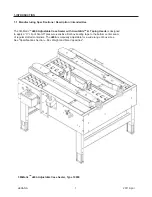
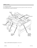
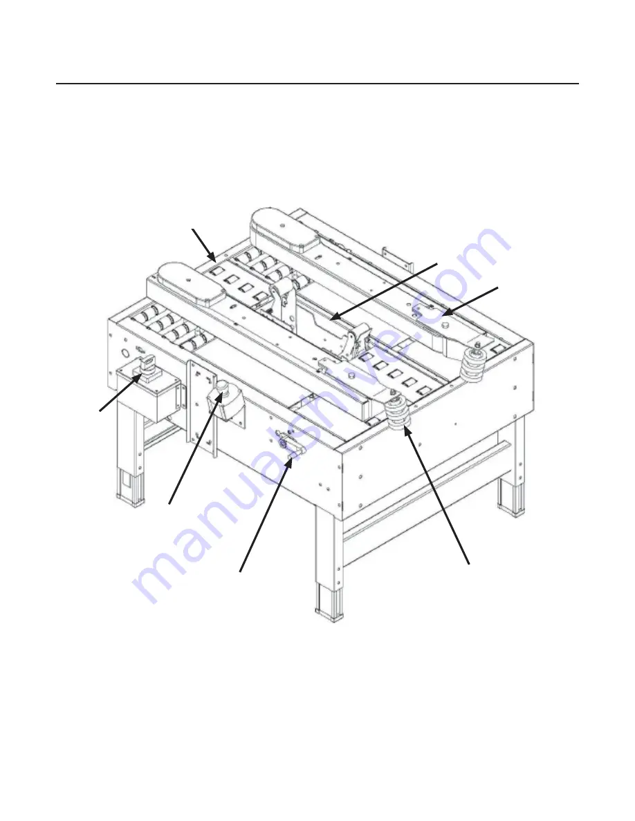
Refer to 

Figure 3-8

 below to acquaint yourself with the various components and controls of the case sealer. 

Also refer to Manual 2 for taping head components.

Figure 3-8—a80b Case Sealer Components  

(Left Front View)

a80b-NA

3.12  Component Locations

Belt Guard

Adjustable
Side Guides
with Box
Drive Belts

 Lower
 Taping Head

 Power Switch 

 Assembly

Drive Belt
Adjustment
Handle

Emergency
Stop 
Switch

 Machine

 Bed

Содержание 3M-Matic a80b

Страница 1: ...here Important Safety Information Spare Parts 3M Matic BEFORE INSTALLING OR OPERATING THIS EQUIPMENT Read understand and follow all safety and operating instructions It is recommended you immediately order the spare parts listed in the Spare Parts Service Information section These parts are expected to wear through normal use and should be kept on hand to minimize production delays 3M Industrial A...

Страница 2: ...tenance troubleshooting repair work and servicing plus parts list of the 3M MaticTM a80b Adjustable case sealer 3M Industrial Adhesives and Tapes 3M Center Building 220 5E 06 St Paul MN 55144 1000 Edition April 2011 Copyright 3M 2011 All rights reserved The manufacturer reserves the right to change the product at any time without notice i ...

Страница 3: ...rts and Additional Manuals Call the 3M Matic Help line at 1 800 328 1390 Provide the customer support coordinator with the model machine name machine type and serial number that are located on the identification plate For example Model a80b Type 10800 Serial Number 13282 Identification Plate Replacement Parts and Service Information 3M Matic AccuGlide and Scotch are Trademarks of 3M St Paul MN 551...

Страница 4: ...THIS PAGE IS BLANK ...

Страница 5: ...y Information 5 3 2 Signal Words Explanation 5 3 3 Table of Warnings 6 7 3 4 Operator s Qualifications 8 3 5 Number of Operators 8 3 6 Safe Use of the Machine Instructions 8 3 7 Residual Hazards 8 3 8 Prevent Other Hazards Recommendations and Measures 8 3 9 Personal Safety Measures 8 3 10 Incorrect Predictable Actions Not Allowed 8 3 11 Operator s Required Skill Levels 9 3 12 Component Locations 1...

Страница 6: ...6 THIS PAGE IS BLANK ...

Страница 7: ...5 Plastic Ties Removal 18 7 6 Assembly Completion 18 7 7 Taping Heads Completion 19 7 8 Preliminary Electric Inspection 19 7 9 Main Power Machine Connection and Inspection 19 7 10 Inspection of Phases 19 8 Theory of Operation 8 1 Working Cycle Description 20 8 2 Running Mode Definition 20 8 3 1 Normal Stop Procedure 20 8 3 2 Emergency Stop 20 9 Controls 9 1 Box Width Adjusting Knobs 21 9 2 On Off ...

Страница 8: ...THIS PAGE IS BLANK ...

Страница 9: ...chine Cleaning 27 13 7 Cutter Blade Cleaning 27 13 8 Lubrication 27 13 9 Lubrication Products 27 13 10 Drive Belt Replacement 28 13 11 Box Drive Belt Tension and Drive Pulley Ring 29 13 12 Maintenance Work Log 30 14 Additional Instructions 14 1 Machine Disposal Information 31 14 2 Fire emergency 31 15 Special Information 15 1 Statement of Conformity 31 15 2 Hazardous Substances Emission 31 15 3 Sa...

Страница 10: ... Paul MN 55144 1000 Drw drawing Ex for example Figure exploded view figure no spare parts Figure Illustration Max maximum Min minimum Nr number N A not applicable OFF machine not operating ON machine operating PLC Programmable Logic Control PP Polypropylene PU PU Foam Polyurethane Foam PTFE Polytetraflourethelene PVC Poly vinyl chloride W Width H Height L Length a80b NA 2011 April ...

Страница 11: ...ure sensitive film box sealing tape to the bottom center seam of regular slotted containers The a80b is manually adjustable for a wide range of box sizes See Specifications Section Box Weight and Size Capacities 3M Matic TM a80b Adjustable Case Sealer Type 10800 1 1 Manufacturing Specifications Description Intended Use a80b NA 2011 April ...

Страница 12: ...ms are included in the manual Equipment using PLC controls and or electronic components will include relevant schematics or programs in the enclosure and in addition the relevant documentation will be delivered separately 1 INTRODUCTION continued 1 2 2 Manual Maintenance Keep the manual in a clean and dry place near the machine Do not remove tear or rewrite parts of the manual for any reason Use t...

Страница 13: ...2 GENERAL INFORMATION 3 2 1 Data Identifying Manufacturer and Machine 2011 April a80b NA For Industrial Use Only ...

Страница 14: ... at 3M s option to repair or replace the part provided the defective part is returned immediately to 3M s factory or an authorized service station designated by 3M A part will be presumed to have become defective after its warranty period unless the part is received or 3M is notified of the problem no later than five 5 calendar days after the warranty period If 3M is unable to repair or replace th...

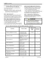
Страница 15: ...ne has a pneumatic system Keep this manual in a handy place near the machine This manual contains information that will help you to maintain the machine in a good and safe working condition 3 SAFETY 3 2 Explanation of Signal Word and Possible Consequences Indicates a potentially hazardous situation which if not avoided may result in minor or moderate injury and or property damage CAUTION Indicates...

Страница 16: ...and disconnect before performing any adjustments maintenance or servicing the machine or taping heads To reduce the risk associated with pinches and entanglement hazards Do not leave the machine running while unattended Turn the machine off when not in use Never attempt to work on any part of the machine load tape or remove jammed boxes from the machine while the machine is running To reduce the r...

Страница 17: ...blade guards The blades are extremely sharp WARNING WARNING WARNING To reduce the risk associated with fire and explosion hazards Do not operate this equipment in potentially flammable explosive environments To reduce the risk associated with muscle strain Use the appropriate rigging and material handling equipment when lifting or repositioning this equipment Use proper body mechanics when removin...

Страница 18: ...ty of the user to appoint the operators having the appropriate skill level and the appropriate training for each category of job To reduce the risk associated with mechanical and electrical hazards Read understand and follow all safety and operating instructions before operating or servicing the case sealer Allow only properly trained and qualified personnel to operate and service this equipment W...

Страница 19: ...ipment etc Skill 3 Specialist from the Manufacturer Skilled operator sent by the manufacturer or its agent to perform complex repairs or modifications on agreement with the customer 3 11 Operator s Skill Levels Required to Perform the Main Operations on the Machine The Table shows the minimum operator s skill for each machine operation Important The factory manager must ensure that the operator ha...

Страница 20: ...ols of the case sealer Also refer to Manual 2 for taping head components Figure 3 8 a80b Case Sealer Components Left Front View a80b NA 3 12 Component Locations Belt Guard Adjustable Side Guides with Box Drive Belts Lower Taping Head Power Switch Assembly Drive Belt Adjustment Handle Emergency Stop Switch Machine Bed ...

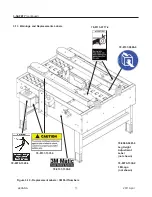
Страница 21: ...M Logo not shown 78 8060 8481 6 78 8070 1339 2 78 8070 1329 3 3 SAFETY continued 2011 April a80b NA 3 13 Warnings and Replacements Labels Figure 3 10 Replacement Labels 3M Part Numbers 78 8137 1331 6 78 8137 1330 8 78 8137 0886 0 78 8113 6717 2 ...

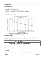
Страница 22: ...m 36mm 1 1 2 inches Maximum 48mm 2 inches 4 4 Tape Scotch pressure sensitive film box sealing tapes 4 3 Operating Conditions Use in dry relatively clean environments at 4 4o C to 48 9o C 40o F to 120o F with clean dry boxes Note Machine should not be washed or subjected to conditions causing moisture condensation on components To reduce the risk associated with fire and explosion hazards Do not op...

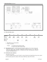
Страница 23: ...pport flaps B Box Size Minimum Maximum Length 152mm 6 0 inch Unlimited Width 121mm 4 75 inch 546mm 21 5 inch Height 70mm 2 75 inch 570mm 22 5 inch Cartons narrower than 250mm 10 inches in width may require more frequent belt replacement because of limited contact area 90mm 3 5 inches height with heads adjusted to apply 50mm 2 inches tape leg lengths See Removing Taping Heads Procedure Changing the...

Страница 24: ...Acoustic pressure measured at a distance of 1m from machine with Scotch PVC adhesive tape in operation 78dB Acoustic radiation pressure at 1 6m height with Scotch PVC adhesive tape in operation 73dB Measurement taken with appropriate instrument Type SPYRI MICROPHON 11 4 12 Buildup Recommendations Machine must be level Customer supplied infeed and exit conveyors if used should provide straight and ...

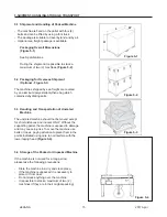
Страница 25: ... Transportation of Uncrated Machine The uncrated machine should not be moved except for short distances and indoors ONLY Without the supporting pallet the machine is exposed to damage and may cause injuries To move the machine use belts or ropes paying attention to place them in the points indicated using care to not interfere with the lower taping head Figure 5 4 5 4 Storage of the Packed or Unpa...

Страница 26: ... pallet Cardboard shipping box Wooden supports Metal fixing brackets PU foam protection PP plastic straps Dehydrating salts in bag Special bag of laminated polyester aluminium Polyethylene sea freight package only Polyethylene protective material For the disposal of the above materials please follow the environmental directives or the law in your country 6 UNPACKING Figure 6 1 Figure 6 3 Figure 6 ...

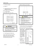
Страница 27: ... inches B 0 7m 27 6 inches Minimum height 2 7m 106 3 inches 7 3 Tool Kit Supplied with the Machine 7 4 Machine Positioning Bed Height 7 INSTALLATION Figure 7 1 2011 April a80b NA To reduce the risk associated with mechanical and electrical hazards Read understand and follow all safety and operating instructions before operating or servicing the case sealer WARNING To reduce the risk associated wit...

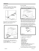
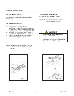
Страница 28: ... taping head in position Hold taping head buff ing roller while cutting the plastic tie Allow buff ing applying arms to extend slowly Figure 7 5 2 Verify that the taping heads moves freely by pushing the buffing roller into the taping head 3 Ensure that the tape drum bracket assembly located on the taping head is mounted vertically as shown in Figure 7 6 Note The tape drum bracket assembly may be ...

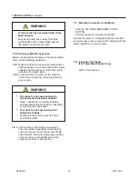
Страница 29: ...The blades are extremely sharp WARNING 7 9 Machine Connection to the Mains Push the LATCHING EMERGENCY STOP BUTTON The main switch is normally turned OFF Connect the power cord supplied with the machine to a wall socket using a plug which complies with the safety regulations of your country 7 8 3 The machine is fitted with a main switch The user will be responsible for testing the short circuit cu...

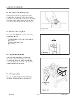
Страница 30: ...atic operating mode with The EMERGENCY STOP BUTTON unlocked Figure 8 1 The main rotary switch ON Figure 8 2 8 3 1 Normal Stop Procedure When the rotary main switch is turned OFF the machine stops immediately at any point of the working cycle The same thing happens in case of electrical failure or when the machine is disconnected from the mains 8 3 2 Emergency Stop The latching EMERGENCY STOP BUTTO...

Страница 31: ...9 CONTROLS 21 9 1 Box Width Adjusting Knobs 9 2 On Off Power Switch 9 3 Latching Emergency Stop Button Figure 9 2 Figure 9 3 2011 April Figure 9 1 a80b NA Power Switch E Stop Location ...

Страница 32: ... clockwise to release the switch latch Restart machine by pushing the Start button Figure 10 1 10 3 Electric System Circuit Breaker The electric system is protected by a ground wire whose continuity has been tested during the final inspection The system is also subject to insulation and dielectric strength tests Important The use of an extension cord is not recommended However if one is needed for...

Страница 33: ...rt assembly as boxes are transported through the machine Keep hands hair loose clothing and jewelry away from box compression rollers Always feed boxes into the machine by pushing only from the end of the box Keep hands hair loose clothing and jewelry away from moving belts and taping heads CAUTION 11 3 Run Boxes to Inspect Adjustment Figure 11 3 Turn electrical switch to On to start drive belts M...

Страница 34: ...justments 12 2 Starting the Machine Important Before starting the machine verify that no tools or other objects are on the conveyor bed Turn the main rotary switch ON after the EMER GENCY BUTTON is released Figure 12 3 12 3 Starting Production After having adjusted the machine according to the box dimensions height width let the machine run without cartons and check its safety devices Then start t...

Страница 35: ...t too high Worn or missing friction rings Drive belt tension too low Electrical disconnect Motor not turning Circuit breaker Motor capacitor Motor fan cover dented Worn belt Improper setup causing boxes to jam Check machine specifications Boxes are narrower than recommended causing slippage and premature belt wear Replace drive belts or friction rings Replace spring holder Reduce spring pressure R...

Страница 36: ...the control panel During the maintenance operation only the operator responsible for this duty must work on the machine At the end of every maintenance operation check the safety devices 13 MAINTENANCE AND REPAIRS 13 5 Check Efficiency of Safety Features 1 Blade guard assembly upper taping head 2 Blade guard assembly lower taping head 3 Emergency stop button with mechanical lock interrupt supply o...

Страница 37: ...of tape adhesive Figure 13 1 Worn or damaged cutter blades must be replaced promptly in order to guarantee a perfect cut of the tape Lubricate the felt pad on the blade guard without saturating it 13 8 Lubrication Most of the machine bearings including the drive motor are permanently lubricated and sealed and do not require additional lubricant 13 MAINTENANCE AND REPAIRS continued Figure 13 1 2011...

Страница 38: ...e new belt Attach the new belt to the old belt and pull the new belt into the position while simultaneously removing the old belt 4 If using the old belt continue with the next step If the old belt cannot be used to install a new belt remove the Belt Drive Cover with a Phillips Screwdriver Figure 13 5 5 Place new belt over pulleys with laced splice at top 6 Insert splicing pin Important Pin must n...

Страница 39: ...s obtained by tightening the adjustment screw so that a moderate pulling force of 3 5kg 7 lbs applied at the mid span as shown in Figure 13 7 will deflect the belt 25mm 1 inch This will assure positive contact between the belt and the drive pulley on the discharge end of the drive assembly Figure 13 7 Box Drive Belt Tension Adjustment To reduce the risk associated with mechanical and electrical ha...

Страница 40: ..._______ ________________________________________________________________ ________ ________________________________________________________________ ________ ________________________________________________________________ ________ ________________________________________________________________ ________ ________________________________________________________________ ________ ______________________...

Страница 41: ...Section 1 1 15 2 Emission of Hazardous Substances Nothing to report 15 3 List of Safety Features List of components assemblies with safety functions Emergency Stop Button with Mechanical Lock Thermal cut out relay Fixed guards upper drive belts Blade guard assemblies on both taping heads Important Install earth wire protection on electrical installation All safety features components must be expla...

Страница 42: ...32 THIS PAGE IS BLANK ...

Страница 43: ...33 2011 April a80b NA 16 TECHNICAL DIAGRAMS continued 16 1 Electric Diagram ...

Страница 44: ...re parts be ordered and kept on hand a80b Qty 3M Part Number Description 2 78 8076 5452 6 Belt Drive with Pin 16 TECHNICAL DOCUMENTATION AND INFORMATION continued 2011 April a80b NA Replacement Parts Ordering Information and Service Refer to the first page of this instruction manual Replacement Parts and Service Information Tool Kit A tool kit part number 78 8060 8476 6 is available as a stock ite...

Страница 45: ...erence number 3 The Parts List that follows each illustration includes the Reference Number Part Number and Part Description for the parts on that illustration Note The complete description has been included for standard fasteners and some commercially availa ble components This has been done to allow obtaining these standard parts locally if desired 4 Order parts by Part Number Part Description a...

Страница 46: ...36 THIS PAGE IS BLANK ...

Страница 47: ...37 2011 April a80b NA a80b Figure 10915 Figure 10914 Frame Assemblies Figure 10916 Figure 10865 ...

Страница 48: ...38 2011 April a80b NA Figure 10865 24 5 7 9 21 21 23 3 2 1 8 13 12 13 27 22 26 20 18 19 17 16 15 14 25 28 11 a80b 6 4 ...

Страница 49: ...7949 9 Screw Soc Hd Hex Soc M5X12 10865 12 78 8137 0916 5 Junction sleeve 10865 13 78 8119 8994 2 Set Screw M5x8 10865 14 78 8137 0917 3 Supporting nut 10865 15 78 8129 6126 2 Nut 10865 16 78 8137 0918 1 Special spring 10865 17 78 8137 0919 9 Driving bush spring 10865 18 78 8137 0920 7 Screw Handle LH 10865 19 78 8137 0921 5 Screw Handle RH 10865 20 78 8137 0922 3 Pin 4X20 10865 21 78 8129 6113 0 ...

Страница 50: ...4 1 37 57 29 48 88 17 50 49 50 49 52 53 40 41 25 27 36 15 16 21 20 20 26 32 21 20 20 26 34 33 31 26 30 42 39 23 9 10 7 92 51 3 5 90 89 89 89 18 22 28 56 54 5 6 8 14 13 87 86 57 4 2 43 44 1 35 47 46 45 24 19 30 38 11 12 91 85 84 92 92 93 93 ...

Страница 51: ...0XL050 10914 18 78 8060 8134 1 Wrap Pulley Ass Y 10914 19 78 8018 7881 6 Belt Timing 21 L050 10914 20 26 1000 0010 3 Washer Flat M6 10914 21 78 8032 0375 7 Screw Metric M6X16 Hex Hd 10914 22 78 8054 8885 1 Pulley Timing 14 Teeth For 10914 23 26 1003 8816 9 Screw Set M5X6 10914 24 78 8060 8136 6 Drive Pulley Ass Y Keyed 10914 25 78 8054 8877 8 Washer 5 5 20X4 10914 26 26 1003 5829 5 Screw Hex Hd M6...

Страница 52: ...42 2011 April a80b NA a80b 60 59 67 65 63 80 80 79 82 83 77 76 76 78 81 70 69 71 64 72 73 74 75 66 70 69 68 65 58 61 62 24 59 28 18 2 29 77 4 51 Figure 10914 ...

Страница 53: ... 10mm 10914 65 26 1000 6036 2 Bearing 6003 2RS 10914 66 78 8060 7547 5 Spacer 10914 67 78 8054 8889 3 Support Pulley Keyed 10914 68 78 8060 8005 3 Sprocket 3 8 11 TEETH 10914 69 78 8054 8877 8 Washer 5 5 20 x 4 10914 70 26 0001 5862 1 Screw Flat Hd Soc M5 x 12 10914 71 78 8091 0525 3 Shaft Pulley 10914 72 78 8091 0524 6 Pulley Jockey 10914 73 78 8060 8008 7 Bearing 6004 2RS 10914 74 78 8060 8010 3...

Страница 54: ... Figure 10915 a80b 8 14 16 3 15 10 14 12 9 11 26 22 21 13 14 13 15 17 13 24 23 25 20 31 32 5 1 5 1 4 5 1 5 1 2 3 4 4 3 3 3 29 28 1 4 24 27 2 4 2 5 33 30 6 3 7 1 2 4 27 21 22 25 24 23 3 18 13 19 18 13 19 20 18 13 19 18 13 19 ...

Страница 55: ...llers Assy 10915 25 78 8137 0848 0 Roller 10915 26 78 8076 4702 5 Grommet 10915 27 78 8060 7758 8 Grommet 10915 28 78 8137 0609 6 Switch E Stop 40 800FM MT44 10915 29 78 8137 0797 9 Terminal Switch 10915 30 78 8129 6469 6 Nut Special M20 10915 31 78 8137 0607 0 Grip Cord Skintop St 20 10915 32 78 8134 1975 7 Wire 10915 33 78 8137 0608 8 Box E Stop Yellow Allen Bradley 10915 34 TBA Support E Stop 1...

Страница 56: ...46 2011 April a80b NA Figure 10916 a80b ...

Страница 57: ...Knob Allen Bradley 10916 4 78 8137 0602 1 Cover 10916 5 78 8094 6145 8 Screw Phillips M5 10916 4 78 8137 0603 9 Switch Terminal Allen Bradley 10916 5 78 8137 0604 7 Coil Under Voltage 120V 60 Hz 10916 8 78 8094 6384 3 Terminal 10916 9 78 8137 0896 9 Box Switch 10916 10 78 8028 7909 4 Power Cord 10916 11 78 8060 8053 3 Wire 10916 12 26 1003 7957 2 Screw M6 10916 13 26 1000 0010 3 Washer Flat M6 ...

Страница 58: ...48 THIS PAGE IS BLANK ...

Отзывы: