3M 3M-Matic 8000a Скачать руководство пользователя страница 47

NA - ENG

April 2016

3M-Matic

 8000a-8000a3 

Page 35

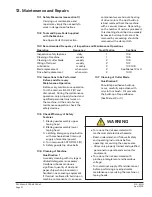
13.11  Taping Heads (Refer to 


Figure 13-5A, 13-5B, and 13-5C)


Note  –

   Changing tape leg to  


48mm [2 inches] requires 


machine adjustment also.  


See Manual 2 or 3 


 “Special 

Set-Up 

Procedure


 Changing ape Leg Length”.


1.  Loosen, but do not remove, the two 


  retaining screws that secure upper 


  taping head shown - 

Figure 13-5A.


2. Hold upper taping head applying 


and 

bu

ffi

  ng arms from under upper 


  assembly, slide head forward and 


down 

to 

remove 

Figure 13-5B

.


3. Lift the lower taping head, shown in 


Figure 13-5C,

 straight up to remove


   it from the case sealer bed.


4. Refer to Manual 2 (Taping Head), 


  See “Adjustments – Changing Tape


  Leg Length” for taping head set-up.

Taping Head Adjustments

Tape Web Alignment  

– Manual 2

Tape Drum Friction Brake  

– Manual 2

Applying Mechanism Spring    – Manual 2
One Way Tension Roller  

– Manual 2

Tape Leg Length  

– Manual 2

Leading Tape Leg Length Adjust – Manual 2
Changing Tape Leg Length from 
   70 to 48mm [2-3/4 to 2 inches] – Manual 2

13. Maintenance and Repairs  

(continued)

• To reduce the risk associated with 

sharp blade hazards:

-   Keep hands and 

fi

 ngers away from 

tape cuto

ff

  blades under orange blade 

guards.  The blades are extremely 
sharp.

 WARNING

Figure 13-5   Removing Taping Heads From Case Sealer


A

C

B

Содержание 3M-Matic 8000a

Страница 1: ...perating instructions Spare Parts It is recommended you immediately order the spare parts listed in the Spare Parts Service Information section These parts are expected to wear through normal use and...

Страница 2: ...NA ENG April 2016 3M Matic 8000a 8000a3 Page ii...

Страница 3: ...Commercial Use Only Technical Assistance Replacement Parts and Additional Manuals Fortechnical assistance contact our help line at 1 800 328 1390 Provide the customer support coordinator with the mode...

Страница 4: ...NA ENG April 2016 3M Matic 8000a 8000a3 Page iv...

Страница 5: ...equipment and you desire a service call or phone consultation call write or fax the appropriate number listed below Included with each machine is an Instructions and Parts List Manual Order parts by p...

Страница 6: ...NA ENG April 2016 3M Matic 8000a 8000a3 Page vi...

Страница 7: ...3 5 Number of Operators 8 3 6 Safe Use of the Machine Instructions 8 3 7 Residual Hazards 8 3 8 Prevent Other Hazards Recommendations and Measures 8 3 9 Personal Safety Measures 8 3 10 Incorrect Pred...

Страница 8: ...NA ENG April 2016 3M Matic 8000a 8000a3 Page viii...

Страница 9: ...nd Inspection 20 7 11 Phases Inspection 20 8 Theory of Operation 8 1 Working Cycle Description 21 8 2 Running Mode Definition 21 8 3 1Normal Stop Procedure 21 8 3 2Emergency Stop 21 9 Controls 9 1 Box...

Страница 10: ...NA ENG April 2016 3M Matic 8000a 8000a3 Page x...

Страница 11: ...eaning 31 13 7 Cutter Blade Cleaning 31 13 8 Drive Belt Replacement 32 33 13 9 Drive Pulley Ring 33 13 10 Box Drive Belt Tensioning 34 13 11 Special Set Up Procedure Taping Heads 35 13 12 Maintenance...

Страница 12: ...44 1000 Scotch Trademark of 3M St Paul MN 55144 1000 Drw Drawing Ex For Example Fig Exploded View Figure no spare parts Figure Illustration Max Maximum Min Minimum Nr Number N A Not Applicable OFF Mac...

Страница 13: ...Scotch pressure sensitive film box sealing tape to the top and bottom center seam of regular slotted containers The 8000a 8000a3 is manually adjustable to a wide range of box sizes see Specifications...

Страница 14: ...l is passed on Electrical and pneumatic diagrams are included in the manual Equipment using PLC controls and or electronic components will include relevant schematics or programs in the enclosure and...

Страница 15: ...16 3M Matic 8000a 8000a3 Page 3 2 General Information 2 2 Data for Technical Assistance and Service Agent Distributor or Local After Sale Service 2 1 Data Identifying Manufacturer and Machine For Comm...

Страница 16: ...nated by 3M A part will be presumed to have become defective after its warranty period unless the part is received or 3M is notified of the problem no later than five 5 calendar days after the warrant...

Страница 17: ...nd or property damage This safety alert symbol identifies important messages in this manual READ AND UNDERSTAND THEM BEFORE INSTALLING OR OPERATING THIS EQUIPMENT Caution Warning Figure 3 1 E Stop Swi...

Страница 18: ...ing while unattended Turn the machine off when not in use Never attempt to work on any part of the machine load tape or remove jammed boxes from the machine while the machine is running WARNING To red...

Страница 19: ...ollers Always feed boxes into the machine by pushing only from the end of box To reduce the risk associated with muscle strain Use appropriate rigging and material handling equipment when lifting or r...

Страница 20: ...n in the Operation Section He must never touch the running driving belts or put his hands inside any cavity The operator must pay attention to the blades during the tape replacement 3 9 Personal Safet...

Страница 21: ...ectrical components Skill 2a Electrical Maintenance Technician This operator is trained to use the machine as the MACHINE OPERATOR and in addition is able to Work with the safety protection disconnect...

Страница 22: ...al 2 for taping head components Figure 3 9 8000a 8000a3 Case Sealer Components Left Front View Upper Taping Head Lower Taping Head Height Adjustment Handle Electrical On Off Switch Width Adjustment Cr...

Страница 23: ...acements Labels continued Leg Height Adjustment Label not shown 3M Logo not shown 78 8060 8481 6 78 8137 7404 5 78 8070 1336 8 2 78 8070 1329 3 78 8137 1331 6 STOP 78 8070 1366 5 78 8137 0886 0 78 809...

Страница 24: ...erating Conditions Use in dry relatively clean environments at 5o C to 50o C 40o F to 120o F with clean dry boxes Note Machine should not be washed or subjected to conditions causing moisture condensa...

Страница 25: ...ch 25 inch See Removing Taping Heads Procedure Changing the Tape Leg Length 4 10 Box Board Style regular slotted containers RSC 125 to 275 P S I bursting test single wall or double wall B or C flute 2...

Страница 26: ...ping heads Special modifications may be available for carton sizes not listed on previous page Contact your 3M Representative for information Note The case sealer can accommodate most boxes within the...

Страница 27: ...35 Right Side C B H F F F A A Optional Casters Control Side Optional Infeed Conveyor Optional Infeed Conveyor Optional Exit Conveyor Optional Exit Conveyor Box Travel W Infeed Exit conveyors are opti...

Страница 28: ...and Transportation of Uncrated Machine The uncrated machine should not be moved except for short distances and indoors ONLY Without the supporting pallet the machine is exposed to damage and may caus...

Страница 29: ...val of Pallet Loosen and remove nuts and brackets using the open end spanner supplied in the tool box Figure 6 4 A cardboard box is located under the machine body Retrieve instruc tion manual for addi...

Страница 30: ...omer will be required for machine maintenance 7 4 Machine Set Up Bed Height 1 Lift the machine with belts or ropes paying attention to place belts in the points Figure 7 2 To set the machine bed heigh...

Страница 31: ...strip and the EMERGENCY STOP cable to the frame Figure 7 5 Cut the plastic ties holding the lower taping head in position Figure 7 6 7 6 Assembly Completion 1 Handle Remove handle from shipping posit...

Страница 32: ...ing head from the machine 2 Remove the tape drum bracket assembly stud spacer and fast eners from the lower taping head 3 Install alternative wrap roller and bracket on the head in place of tape brack...

Страница 33: ...r 8 2 Definition of Running Mode The case sealer 8000a 8000a3 has only one automatic operating mode with The EMERGENCY STOP BUTTON unlocked Figure 8 1 The main switch On Off ON I Figure 8 2 8 3 1 Norm...

Страница 34: ...atic 8000a 8000a3 Page 22 9 Controls 9 1 Box Width Adjusting Knobs 9 2 Box Height Adjusting Crank 9 3 On Off Switch 9 4 Latching Emergency Stop Button On Off Switch Figure 9 3 Figure 9 4 Figure 9 1 E...

Страница 35: ...overloaded Located inside the electrical enclosure on the side of the machine frame just below the machine bed the circuit breaker has been pre set and requires no further maintenance If circuit is o...

Страница 36: ...ox flaps closed Figure 11 2 11 3 Adjustment of Top Flap Compression Rollers The top flap compression rollers have an adjustable slide mounting to provide side compression through the full range of box...

Страница 37: ...head assembly down until it touches these blocks 3 Loosen but do not remove the eight 8 screws and washers that fasten each column to the frame Figure 11 7B Note You will also need to loosen the two...

Страница 38: ...justment can be made by moving the Upper Assembly Crossbar up to top holes Figure 11 8 11 6 Run Boxes to Check Adjustment Turn electrical switch On I to start drive belts Move box forward under upper...

Страница 39: ...ng cycle 12 4 Tape Replacement and Threading Skill 1 Operator See Manual 2 or 3 AccuGlide 3 High Speed 2 Inch or 3 Inch Taping Heads Press the LATCHING EMERGENCY STOP BUTTON 12 5 Box Size Adjustment R...

Страница 40: ...er missing Taping head applying spring set too high Worn or missing friction rings Drive belt tension too low Electrical disconnect Motor not turning Release the emergency stop button Check the electr...

Страница 41: ...not rotate freely The blade is not cutting tape properly The tape is threaded incorrect Applying mechanism spring has too little tension Replace the blade Increase tape tension by adjusting the one wa...

Страница 42: ...NA ENG April 2016 3M Matic 8000a 8000a3 Page 30...

Страница 43: ...onent wear and over heating of drive motors The dust build up is best removed from the machine with a vacuum cleaner Depending on the number of cartons processed this cleaning should be done weekly Ex...

Страница 44: ...ocate the belt lacing joint by turning the belt manually Remove the pin with pliers Remove and discard old belt continued on next page 13 Maintenance and Repairs continued To reduce the risk associate...

Страница 45: ...pan as shown with a moderate pulling force of 3 5 kg 7 lbs 8 Reverse procedures in Steps 1 3 Figure 13 1 to reassemble the drive belt assembly 13 9 Box Drive Pulley Rings Before installing a new belt...

Страница 46: ...ll assure positive contact between the belt and the drive pulley on the discharge end of the taping head To adjust belts see Maintenance Drive Belts steps 3 and 7 13 Maintenance and Repairs continued...

Страница 47: ...Figure 13 5C straight up to remove it from the case sealer bed 4 Refer to Manual 2 Taping Head See Adjustments Changing Tape Leg Length for taping head set up Taping Head Adjustments Tape Web Alignme...

Страница 48: ...NA ENG April 2016 3M Matic 8000a 8000a3 Page 36...

Страница 49: ...______________ ________ _____________________________________________________ ________ _____________________________________________________ ________ __________________________________________________...

Страница 50: ...on pulleys For machine disposal follow the regulations published in each country 14 2 Emergency Procedures In case of danger fire Disconnect plug of power cable from power supply Figure 14 1 IN CASE O...

Страница 51: ...6 3M Matic 8000a 8000a3 Page 39 16 1 Technical Diagrams Electric 1 L1 N 1 2 N N 5 6 1 1 115V 1Ph 60Hz 2 PE M1 M1 M1 SB1 EStop U1 U1 V1 V1 PE QM1 D1 U1 D2 PE PE PE PE M2 M M 16 Technical Documentation...

Страница 52: ...8000a3 Adjustable Case Sealer It is suggested that the following spare parts be ordered and kept on hand continued 8000a 8000a3 Qty 3M Part Number Description 2 78 8076 5452 6 Belt Drive w Hook Spare...

Страница 53: ...al Replacement Parts and Service Information for replacement parts ordering information Important Not all the parts listed are normally stocked items Some parts or assemblies shown are available only...

Страница 54: ...NA ENG April 2016 3M Matic 8000a 8000a3 Page 42...

Страница 55: ...ril 2016 3M Matic 8000a 8000a3 Page 43 8000a 8000a3 Frame Assemblies Figure 15967 Figure 15964 Figure 15978 Figure 15946 Figure 15971 Figure 15969 Not Shown Figure 15968 Figure 15968 Figure 15870 Figu...

Страница 56: ...NA ENG April 2016 3M Matic 8000a 8000a3 Page 44 8000a 8000a3 Figure 15870 2 7 5 2 9 13 12 11 10 1 6 5 9 5 4 3 8 6...

Страница 57: ...881 4 Pin Compression Roller 15870 5 26 1004 5510 9 Washer M10 Galvanized 15870 6 26 1003 6918 5 Nut M10 Self Locking 15870 7 26 1004 5507 5 Triple Washer M8 Galvanized 15870 8 26 1003 5841 0 Screw M8...

Страница 58: ...6 3M Matic 8000a 8000a3 Page 46 8000a 8000a3 Figure 15967 21 19 8 8 8 17 12 4 10 18 16 11 7 3 5 14 15 6 9 13 2 21 6 21 1 20 Note See Parts List for Accuglide 2 and 3 information Note Part Number 19 3...

Страница 59: ...4 Leaf Spring 3 15967 8 26 1002 5753 9 Screw Self Tapping 7SPX8 15967 9 78 8060 8172 1 Washer Friction 15967 10 78 8052 6271 0 Washer Tape Drum 15967 11 78 8100 1048 4 Spring Core Holder 15967 12 78...

Страница 60: ...NA ENG April 2016 3M Matic 8000a 8000a3 Page 48 8000a 8000a3 Figure 15968 6 27 20 29 24 14 13 17 1 4 1 1 2 3 11 7 1 8 9 16 16 25 26 5 23 00 22 18 10 21 15 12 19 12 6 17 26 28 30...

Страница 61: ...064 6 Bracket Cable Chain 15968 14 78 8010 7210 5 Screw M6X20 Soc Hd Hex Soc 15968 15 78 8137 8104 0 Screw M5X12 15968 16 78 8005 5741 1 Washer M5 Flat 15968 17 78 8076 4538 3 Washer M3 Flat 15968 18...

Страница 62: ...e 50 8000a 8000a3 Figure 15963 Conveyors are Optional Casters are Optional 42 43 44 51 37 41 11 4 22 5 1 19 2 21 13 17 7 26 29 32 31 26 23 10 39 38 36 3 46 52 40 16 11 5 30 34 35 25 47 3 48 12 7 8 7 1...

Страница 63: ...te Infeed Conveyor 15963 25 78 8137 7774 1 Pin 8X124 Galvanized 15963 26 78 8060 7693 7 Roller 32X38 15963 27 78 8076 5389 0 Mounting Hardware Conveyor 15963 28 78 8091 0418 1 Nut M6 Self Locking 1596...

Страница 64: ...NA ENG April 2016 3M Matic 8000a 8000a3 Page 52 8000a 8000a3 Figure 15971 17 25 17 18 19 16 14 14 13 21 22 4 5 6 7 3 8 9 10 12 1 2 3 23 11 16 20 24 13 15...

Страница 65: ...1 11 78 8137 5915 2 Connection Sleeve S8 CE 3 15971 12 78 8137 8074 5 Screw Left 15971 13 78 8137 7772 5 Rod Guide 15971 14 78 8094 6230 8 Bearing Bushing KH2030 P 15971 15 78 8137 8075 2 Support 1597...

Страница 66: ...00a 8000a3 Page 54 8000a 8000a3 Figure 15946 4 5 20 28 34 20 32 15 28 30 24 38 22 28 18 3 33 1 29 31 17 23 36 16 19 23 26 22 18 18 35 11 37 26 2 11 28 10 25 29 27 25 29 16 13 40 7 9 14 12 3 33 5 29 18...

Страница 67: ...Support w Bearing 15946 18 78 8137 5905 3 Pinion Conic 15946 19 78 8060 8125 9 Bushing 15946 20 78 8129 6143 7 Bushing 15946 21 78 8129 6118 9 Handle 15946 22 78 8137 6333 7 Plate Screw 15946 23 78 8...

Страница 68: ...re 15964 1 Left 8000a 8000a3 59 60 61 2 1 3 31 17 45 62 8 46 47 48 4 7 25 26 27 57 28 6 52 58 30 56 26 29 54 53 33 33 32 12 34 35 36 37 5 29 16 53 54 38 39 14 24 29 50 9 10 11 12 18 49 15 5 18 19 20 2...

Страница 69: ...78 8010 7193 3 Screw M6X20 Hex Hd 15964 29 26 1000 0010 3 Washer Flat M6 15964 30 78 8137 8021 6 Screw TSVEI 1 4 28 UNF X 3 4 10 9 15964 31 78 8137 8003 4 Shaft 15964 32 78 8057 5739 6 Key M5X5X30mm...

Страница 70: ...0a 8000a3 Figure 15964 2 Right 3 1 2 21 6 7 4 5 46 47 50 45 55 54 22 25 27 23 23 23 21 48 53 56 52 51 52 49 21 4 51 42 40 38 41 39 44 43 39 21 13 38 4 32 33 34 10 12 10 13 8 57 14 4 15 16 17 18 19 20...

Страница 71: ...t 15964 26 78 8057 5739 6 Key M5X5X30mm 15964 27 78 8046 8135 7 Key 5 X 5 12mm 15964 28 78 8137 8024 0 Support 15964 29 78 8137 7946 5 Adjustable Bearing 2202 2RS 15964 30 78 8137 7999 4 E RIng D35 15...

Страница 72: ...NA ENG April 2016 3M Matic 8000a 8000a3 Page 60 14 Figure 15969 8000a 8000a3 15 15 12 11 4 5 12 14 7 13 1 3 10 9 6 8 2...

Страница 73: ...969 5 78 8005 5741 1 Washer M5 Flat 15969 6 78 8010 7417 6 Nut M5 Hex Steel 15969 7 78 8137 7852 5 Bracket Cable Chain 15969 8 78 8137 7853 3 Cover Grey Housing 15969 9 78 8010 7157 8 Screw M4X10 Hex...

Страница 74: ...NA ENG April 2016 3M Matic 8000a 8000a3 Page 62 8000a 8000a3 Figure 15978 15 20 17 16 19 18 13 1 9 6 4 10 8 7 12 11 5 4 3 14 2 2 13 2 14...

Страница 75: ...137 0782 1 Phases Spacer 15978 8 78 8137 8090 1 Cover Electrical Box 15978 9 78 8137 7968 9 Screw M5X16 Galvanized 15978 10 78 8137 7976 1 Box Electrical 15978 11 78 8119 8554 4 Adhesive Rubber Seal 1...

Страница 76: ...NA ENG April 2016 3M Matic 8000a 8000a3 Page 64...

Страница 77: ...safety and operating instructions Spare Parts It is recommended you immediately order the spare parts listed in the Spare Parts Service Information section These parts are expected to wear through nor...

Страница 78: ...NA ENG April 2016 3M Matic Accuglide 3 2 Inch Taping Head Page ii...

Страница 79: ...Technical Assistance Replacement Parts and Additional Manuals Contact your local service provider help line at 1 800 328 1390 Provide the customer support coordinator with the model machine name mach...

Страница 80: ...NA ENG April 2016 3M Matic Accuglide 3 2 Inch Taping Head Page iv...

Страница 81: ...perating this equipment and you desire a service call or phone consultation call write or fax the appropriate number listed below Included with each machine is an Instructions and Parts List Manual Or...

Страница 82: ...NA ENG April 2016 3M Matic Accuglide 3 2 Inch Taping Head Page vi...

Страница 83: ...ation Guidelines 8 Tape Leg Length 8 Tape Width Adjustment 8 Operation 9 11 Tape Loading Upper Taping Head 10 Tape Loading Lower Taping Head 10 11 Maintenance 12 13 Blade Replacement 12 Blade Guard 12...

Страница 84: ...the 3M Matic Help line 800 328 1390 To be entitled to repair or replacement as provided under this warranty the part must be returned as directed by 3M to its factory or other authorized service stati...

Страница 85: ...of regular slotted containers These taping heads are incorporated into most standard 3M Matic case sealers The compact size and simplicity of the taping head also makes it suitable for mounting in bo...

Страница 86: ...NA ENG April 2016 3M Matic Accuglide 3 2 Inch Taping Head Page 2...

Страница 87: ...l is available to all operators of this equipment and the manual is kept up to date with all subsequent amendments Should the equipment be sold or disposed of please ensure that the manual is passed o...

Страница 88: ...er Allow only properly trained and qualified personnel to operate and or service this equipment CAUTION To reduce the risk associated with muscle strain Use proper body mechanics when removing or inst...

Страница 89: ...Numbers Important In the event the following safety labels are damaged or destroyed they must be replaced to ensure operator safety See Replacement Parts Illustrations and Parts Lists for label part...

Страница 90: ...Tape Leg Length 5 Box Size Capacities For use with center seam regular slotted containers When upper and lower taping heads are used on 3M Matic case sealers refer to the respective instruction manua...

Страница 91: ...3 in 6mm 1 4 in Maximum 405mm 16 in Maximum Roll Diameter 405mm 16 in Maximum Roll Diameter 445mm 17 1 2 in 120mm 4 3 4 in Minimum Standard Head Spacing M6 Mounting Holes This dimension can be reduce...

Страница 92: ...ompletely staggered so only one tape seal is being applied at one time Note AccuGlide 3 High Speed Upper Taping Head is supplied with a buffing arm guard Adjustments to guard may be required to instal...

Страница 93: ...e Supply Roll Tape Adhesive Side Tape Adhesive Side Tension Wrap Roller Tension Wrap Roller Knurled Roller Knurled Roller Wrap Roller Wrap Roller Threading Needle Threading Needle Applying Roller Appl...

Страница 94: ...needle down until tape travels between apply plate and ears of apply arm Position 4 until extends past apply roller When threaded adhe sive side of tape should face knurled rollers at position 2 and...

Страница 95: ...flange of drum Adhere tape lead end to threading needle as shown Manually turn tape roll to create slack tape while pulling threading needle through tape applying mechanism until needle is through and...

Страница 96: ...rance between blade and guard by slowly pivoting blade guard back Blade Guard The blade guard covers the blade whenever a box is not being taped Periodically check to be sure the blade guard is functi...

Страница 97: ...t damage Never wash down or subject taping heads to conditions causing moisture condens ation on components Serious equipment damage could result Applying Buffing Roller Replacement Replacing roller r...

Страница 98: ...e an adjustable wrench or 25mm open end wrench 2 Using 5mm Hex Wrench turn tape drum shaft in out to center tape web 3 Tighten locking hex nut to secure the adjustment No other components require adju...

Страница 99: ...igure 5 5 The one way tension roller is factory set When replacing this assembly the roller must have 0 5 kg 1 lb min tangential force when turning To Adjust Tension 1 Wrap a cord or small strap non a...

Страница 100: ...head screws and remove the brush from normal position A on side frame 2 Remount and secure brush in posi tion A A on side frame forward of normal location with original fasteners 3 Remove cut off bra...

Страница 101: ...tension roller Check for adhesive build up between the knurled roller and its shaft Clean and lubricate shaft Remove all lubricant from roller surfaces Adjust the tape web alignments Position the roll...

Страница 102: ...is not correctly positioned The one way tension roller is defective Tape drum not centered Centering guides not centered Box flaps not of equal length Correction Adjust the one way tension roller and...

Страница 103: ...er Taping Head 2 inch Qty Part Number Description 1 78 8017 9173 8 Blade 65mm 2 56 Inch 2 78 8052 6602 6 Spring Cutter 4 78 8076 4500 3 Stud Mounting 1 78 8137 3312 4 Spring Lower Extension 1 78 8076...

Страница 104: ...NA ENG April 2016 3M Matic Accuglide 3 2 Inch Taping Head Page 20...

Страница 105: ...ach illustration includes the part number and part description for the parts in that illustration Note The complete description has been included for standard fasteners and some commercially available...

Страница 106: ...NA ENG April 2016 3M Matic Accuglide 3 2 Inch Taping Head Page 22...

Страница 107: ...il 2016 3M Matic Accuglide 3 2 Inch Taping Head Page 23 Tape Head Figures AccuGlide 3 2 inch AccuGlide 3 2 Figure 10919 Figure 10920 Figure 10921 Figure 10922 Figure 10925 Figure 10923 Figure 10924 Fi...

Страница 108: ...NA ENG April 2016 3M Matic Accuglide 3 2 Inch Taping Head Page 24 AccuGlide 3 2 24 25 1 3 2 4 8 11 10 12 16 15 17 17 18 19 13 13 13 9 7 5 23 13 23 27 20 29 27 26 28 29 21 Figure 10925 Upper Head...

Страница 109: ...er 10925 13 26 1003 5829 5 Screw Hex Hd M6 x 12 10925 15 78 8100 1009 6 Washer Special 10925 16 78 8052 6565 5 Roller Top Tension 10925 17 26 1004 5510 9 Washer Plain M10 10925 18 78 8052 6567 1 Sprin...

Страница 110: ...NA ENG April 2016 3M Matic Accuglide 3 2 Inch Taping Head Page 26 15 14 12 12 11 10 13 15 16 16 1 4 4 3 7 2 5 6 8 8 9 9 Figure 10922 Upper and Lower Heads AccuGlide 3 2...

Страница 111: ...r Knurled Assembly 10922 6 78 8070 1266 7 Roller Wrap 10922 7 78 8052 6580 4 Spacer 10922 8 78 8017 9082 1 Bearing Special 30 mm 10922 9 78 8017 9106 8 Screw Bearing Shoulder 10922 10 78 8052 6575 4 S...

Страница 112: ...NA ENG April 2016 3M Matic Accuglide 3 2 Inch Taping Head Page 28 15 14 12 12 11 10 13 15 16 16 1 4 4 3 7 2 5 6 8 8 9 9 Figure 10919 Upper Head AccuGlide 3 2...

Страница 113: ...Arm Sub Assembly 10919 2 78 8137 3301 7 Buffing Arm Sub Assembly 10919 3 78 8052 6575 4 Shaft Roller 10919 4 78 8137 1398 5 Roller Buffing Assembly 10919 5 78 8070 1220 4 Spacer Spring 10919 6 78 8052...

Страница 114: ...NA ENG April 2016 3M Matic Accuglide 3 2 Inch Taping Head Page 30 Figure 10923 Upper and Lower Heads 1 7 7 3 8 5 5 4 4 9 9 6 6 Figure 10923 Upper and Lower Heads AccuGlide 3 2...

Страница 115: ...Shaft Pivot Buffing 10923 4 78 8017 9082 1 Bearing Special 30 mm 10923 5 78 8017 9106 8 Screw Bearing Shoulder 10923 6 26 1003 5829 5 Screw Hex Hd M6 x 12 10923 7 78 8137 3305 8 Spacer Applying Pivot...

Страница 116: ...NA ENG April 2016 3M Matic Accuglide 3 2 Inch Taping Head Page 32 Figure 10921 Upper and Lower Heads AccuGlide 3 2...

Страница 117: ...ft Blade Guard 10921 7 26 1005 4758 2 Screw Flat Hd Soc Dr M4 x 10 10921 8 78 8017 9135 7 Shaft Spacer 10921 9 78 8052 6600 0 Spacer 10921 10 78 8070 1269 1 Bumper 10921 11 26 1005 4757 4 Screw Flat H...

Страница 118: ...NA ENG April 2016 3M Matic Accuglide 3 2 Inch Taping Head Page 34 Figure 10401 Upper and Lower Heads AccuGlide 3 2 4 14 16 14 3 1 13 13 13 12 13 5 6 7 7 7 2 4 8 9 10 15 11...

Страница 119: ...Wide 10401 5 78 8098 8749 6 Tape Drum 10401 6 78 8098 8817 1 Leaf Spring 10401 7 26 1002 5753 9 Screw Self Tapping 10401 8 78 8060 8172 1 Washer Friction 10401 9 78 8052 6271 0 Washer Tape Drum 10401...

Страница 120: ...NA ENG April 2016 3M Matic Accuglide 3 2 Inch Taping Head Page 36 26 8 2 4 8 13 13 13 13 15 29 29 18 27 24 25 27 28 16 17 17 19 26 9 7 3 1 11 12 10 20 21 23 23 5 Figure 10924 Lower Head AccuGlide 3 2...

Страница 121: ...r 10924 13 26 1003 5829 5 Screw Hex Hd M6 x 12 10924 15 78 8100 1009 6 Washer Special 10924 16 78 8052 6606 7 Roller Tension Bottom 10924 17 26 1004 5510 9 Washer Plain M10 10924 18 78 8052 6567 1 Spr...

Страница 122: ...NA ENG April 2016 3M Matic Accuglide 3 2 Inch Taping Head Page 38 9 6 4 3 2 1 8 5 9 7 7 7 7 7 7 Figure 10920 Lower Head AccuGlide 3 2...

Страница 123: ...rm Sub Assembly 10920 2 78 8137 3301 7 Buffing Arm Sub Assembly 10920 3 78 8052 6575 4 Shaft Roller 10920 4 78 8137 1398 5 Roller Buffing Assembly 10920 5 78 8070 1220 4 Spacer Spring 10920 6 78 8052...

Страница 124: ...NA ENG April 2016 3M Matic Accuglide 3 2 Inch Taping Head Page 40...

Страница 125: ...NA ENG April 2016 3M Matic Accuglide 3 2 Inch Taping Head Page 41...

Страница 126: ...NA ENG April 2016 3M Matic Accuglide 3 2 Inch Taping Head Page 42...

Страница 127: ...safety and operating instructions Spare Parts It is recommended you immediately order the spare parts listed in the Spare Parts Service Information section These parts are expected to wear through no...

Страница 128: ...NA ENG April 2016 3M Matic Accuglide 3 3 Inch Taping Head Page ii...

Страница 129: ...Technical Assistance Replacement Parts and Additional Manuals Contact your local service provider help line at 1 800 328 1390 Provide the customer support coordinator with the model machine name mach...

Страница 130: ...NA ENG April 2016 3M Matic Accuglide 3 3 Inch Taping Head Page iv...

Страница 131: ...perating this equipment and you desire a service call or phone consultation call write or fax the appropriate number listed below Included with each machine is an Instructions and Parts List Manual Or...

Страница 132: ...NA ENG April 2016 3M Matic Accuglide 3 3 Inch Taping Head Page vi...

Страница 133: ...ation Guidelines 8 Tape Leg Length 8 Tape Width Adjustment 8 Operation 9 11 Tape Loading Upper Taping Head 10 Tape Loading Lower Taping Head 10 11 Maintenance 12 13 Blade Replacement 12 Blade Guard 12...

Страница 134: ...the 3M Matic Help line 800 328 1390 To be entitled to repair or replacement as provided under this warranty the part must be returned as directed by 3M to its factory or other authorized service stati...

Страница 135: ...of regular slotted containers These taping heads are incorporated into most standard 3M Matic case sealers The compact size and simplicity of the taping head also makes it suitable for mounting in bo...

Страница 136: ...NA ENG April 2016 3M Matic Accuglide 3 3 Inch Taping Head Page 2...

Страница 137: ...l is available to all operators of this equipment and the manual is kept up to date with all subsequent amendments Should the equipment be sold or disposed of please ensure that the manual is passed o...

Страница 138: ...er Allow only properly trained and qualified personnel to operate and or service this equipment CAUTION To reduce the risk associated with muscle strain Use proper body mechanics when removing or inst...

Страница 139: ...re damaged or destroyed they must be replaced to ensure operator safety See Replacement Parts Illustrations and Parts Lists for label part numbers Important Safeguards continued 78 8070 1335 0 Upper T...

Страница 140: ...ximum Length 150mm 6 inches Unlimited Height 120mm 4 3 4 inches most 3M Matic Case Sealers 90mm 3 1 2 inches with optional 2 inch leg length Width 150mm 6 inches When upper and lower taping heads are...

Страница 141: ...3 in 6mm 1 4 in Maximum 405mm 16 in Maximum Roll Diameter 405mm 16 in Maximum Roll Diameter 445mm 17 1 2 in 120mm 4 3 4 in Minimum Standard Head Spacing M6 Mounting Holes This dimension can be reduce...

Страница 142: ...ompletely staggered so only one tape seal is being applied at one time Note AccuGlide 3 High Speed Upper Taping Head is supplied with a buffing arm guard Adjustments to guard may be required to instal...

Страница 143: ...e Supply Roll Tape Adhesive Side Tape Adhesive Side Tension Wrap Roller Tension Wrap Roller Knurled Roller Knurled Roller Wrap Roller Wrap Roller Threading Needle Threading Needle Applying Roller Appl...

Страница 144: ...needle down until tape travels between apply plate and ears of apply arm Position 4 until extends past apply roller When threaded adhe sive side of tape should face knurled rollers at position 2 and...

Страница 145: ...flange of drum Adhere tape lead end to threading needle as shown Manually turn tape roll to create slack tape while pulling threading needle through tape applying mechanism until needle is through and...

Страница 146: ...rance between blade and guard by slowly pivoting blade guard back Blade Guard The blade guard covers the blade whenever a box is not being taped Periodically check to be sure the blade guard is functi...

Страница 147: ...build up should be wiped off with a damp cloth Cleaning should be done once per month depending on the number and type of boxes used If the boxes used are dirty or if the environment in which the head...

Страница 148: ...e an adjustable wrench or 25mm open end wrench 2 Using 5mm Hex Wrench turn tape drum shaft in out to center tape web 3 Tighten locking hex nut to secure the adjustment No other components require adju...

Страница 149: ...spring pressure see Figure 5 4B One Way Tension Roller Figure 5 5 The one way tension roller is factory set When replacing this assembly the roller must have 0 5 kg 1 lb min tangential force when tur...

Страница 150: ...head screws and remove the brush from normal position A on side frame 2 Remount and secure brush in posi tion A A on side frame forward of normal location with original fasteners 3 Remove cut off bra...

Страница 151: ...ension roller Check for adhesive build up between the knurled roller and its shaft Clean and lubricate shaft Remove all lubricant from roller surfaces Adjust the tape web alignments Position the rolle...

Страница 152: ...is not correctly positioned The one way tension roller is defective Tape drum not centered Centering guides not centered Box flaps not of equal length Correction Adjust the one way tension roller and...

Страница 153: ...er Taping Head 3 inch Qty Part Number Description 1 78 8028 7899 7 Blade 89mm 3 5 Inch 2 78 8052 6602 6 Spring Cutter 4 78 8076 4500 3 Stud Mounting 1 78 8137 3312 4 Spring Lower Extension 1 78 8076 4...

Страница 154: ...NA ENG April 2016 3M Matic Accuglide 3 3 Inch Taping Head Page 20...

Страница 155: ...ach illustration includes the part number and part description for the parts in that illustration Note The complete description has been included for standard fasteners and some commercially available...

Страница 156: ...NA ENG April 2016 3M Matic Accuglide 3 3 Inch Taping Head Page 22...

Страница 157: ...3M Matic Accuglide 3 3 Inch Taping Head Page 23 AccuGlide 3 3 Figure 10926 Upper Figure 10927 Lower Figure 10928 Figure 10929 Figure 10930 Figure 10402 Tape Head AccuGlide 3 3 inch Figure 10932 Upper...

Страница 158: ...NA ENG April 2016 3M Matic Accuglide 3 3 Inch Taping Head Page 24 AccuGlide 3 3 Figure 10932 Upper Head...

Страница 159: ...ew Hex Hd M6 x 12 10932 15 78 8100 1009 6 Washer Special 10932 16 78 8054 8797 8 Roller Top Tension 10932 17 26 1004 5510 9 Washer Plain M10 10932 18 78 8052 6567 1 Spring Compression 10932 19 78 8017...

Страница 160: ...NA ENG April 2016 3M Matic Accuglide 3 3 Inch Taping Head Page 26 AccuGlide 3 3 14 15 15 16 16 Figure 10929 Upper and Lower Heads...

Страница 161: ...4737 1 Roller Assembly Knurled 10929 6 78 8076 4738 9 Roller Wrap 10929 7 78 8054 8806 7 Spacer 10929 8 78 8017 9082 1 Bearing Special 30 mm 10929 9 78 8017 9106 8 Screw Bearing Shoulder 10929 10 78 8...

Страница 162: ...NA ENG April 2016 3M Matic Accuglide 3 3 Inch Taping Head Page 28 AccuGlide 3 3 6 4 3 2 1 8 5 9 7 7 7 7 7 7 Figure 10926 Upper Head...

Страница 163: ...uffing Arm Sub Assembly 10926 2 78 8137 3301 7 Buffing Arm Sub Assembly 10926 3 78 8091 0799 4 Shaft 10 x 85 W Hexagon 10926 4 78 8137 1397 7 Roller Buffing Assembly 10926 5 78 8076 4739 7 Spacer Spri...

Страница 164: ...NA ENG April 2016 3M Matic Accuglide 3 3 Inch Taping Head Page 30 AccuGlide 3 3 Figure 10930 Upper and Lower Heads 1 6 7 7 3 8 5 5 4 4 9 9 6...

Страница 165: ...8137 3302 5 Link R H Assembly 10930 3 78 8137 3314 0 Shaft Pivot Buffing 10930 4 78 8017 9082 1 Bearing Special 30 mm 10930 5 78 8017 9106 8 Screw Bearing Shoulder 10930 6 26 1003 5829 5 Screw Hex Hd...

Страница 166: ...NA ENG April 2016 3M Matic Accuglide 3 3 Inch Taping Head Page 32 AccuGlide 3 3 3 2 4 8 11 12 10 10 11 13 13 14 15 14 15 17 18 16 16 9 9 7 7 5 Figure 10928 Upper and Lower Heads...

Страница 167: ...Guard 10928 7 26 1005 4758 2 Screw Flat Hd Soc Dr M4 x 10 10928 8 78 8060 7941 0 Pin Spring Holder W Slots 10928 9 78 8052 6600 0 Spacer 10928 10 78 8070 1269 1 Bumper 10928 11 26 1005 4757 4 Screw Fl...

Страница 168: ...NA ENG April 2016 3M Matic Accuglide 3 3 Inch Taping Head Page 34 AccuGlide 3 3 Figure 10402 Upper and Lower Heads 4 9 14 20 4 2 8 9 10 17 15 11 16 13 13 13 13 14 12 13 7 7 1 3 7 6 5...

Страница 169: ...ide 10402 5 78 8098 8828 8 Tape Drum 10402 6 78 8098 8830 4 Leaf Spring 10402 7 26 1002 5753 9 Screw Self Tapping 10402 8 78 8060 8172 1 Washer Friction 10402 9 78 8052 6271 0 Washer Tape Drum 10402 1...

Страница 170: ...ENG April 2016 3M Matic Accuglide 3 3 Inch Taping Head Page 36 AccuGlide 3 3 26 8 2 4 8 13 32 13 13 15 29 29 18 27 24 25 27 28 16 17 17 19 26 9 7 3 1 11 12 10 20 21 31 31 23 23 5 Figure 10931 Lower He...

Страница 171: ...ew Hex Hd M6 x 12 10931 15 78 8100 1009 6 Washer Special 10931 16 78 8054 8817 4 Roller Tension Bottom 10931 17 26 1004 5510 9 Washer Plain M10 10931 18 78 8052 6567 1 Spring Compression 10931 19 78 8...

Страница 172: ...NA ENG April 2016 3M Matic Accuglide 3 3 Inch Taping Head Page 38 AccuGlide 3 3 6 4 3 2 1 8 5 9 7 7 7 7 7 7 Figure 10927 Lower Head...

Страница 173: ...0 9 Buffing Arm Sub Assembly 10927 2 78 8137 3301 7 Buffing Arm Sub Assembly 10927 3 78 8091 0799 4 Shaft 10 x 85 W Hexagon 10927 4 78 8137 1397 7 Roller Buffing 10927 5 78 8076 4739 7 Spacer Spring 1...

Страница 174: ...NA ENG April 2016 3M Matic Accuglide 3 3 Inch Taping Head Page 40...

Страница 175: ...NA ENG April 2016 3M Matic Accuglide 3 3 Inch Taping Head Page 41...

Страница 176: ...NA ENG April 2016 3M Matic Accuglide 3 3 Inch Taping Head Page 42...

Отзывы: