


210
C
HAPTER
17: V
IEWING
S
TATISTICS
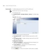
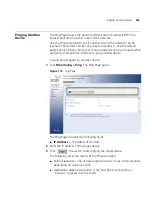
Viewing Port
Statistics
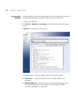
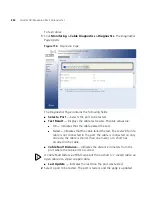
The
Port Statistics Summary Page
contains fields for viewing information
about device utilization and errors that occurred on the device.
To view port statistics:
1
Click
Ports > Statistics > Summary
. The
Port Statistics Summary Page
opens:
Figure 110
Port Statistics Summary Page
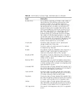
The
Port Statistics Summary Page
contains the following fields:
■
Select Port
— Selects the specific port for which statistics are
displayed.
■
Refresh Interval
— Defines the amount of time that passes before
the interface statistics are refreshed. The field range is
10-600
seconds, and default is
10
seconds.
Содержание 3CRDSF9PWR-US - OfficeConnect Managed Fast Ethernet PoE...
Страница 6: ...6 ABOUT THIS GUIDE...
Страница 14: ......
Страница 102: ...102 CHAPTER 4 MANAGING DEVICE SECURITY...
Страница 112: ...112 CHAPTER 5 MANAGING SYSTEM INFORMATION...
Страница 120: ...120 CHAPTER 6 CONFIGURING PORTS...
Страница 130: ...130 CHAPTER 7 AGGREGATING PORTS 3 Click The LACP Link Aggregation is modified and the application is updated...
Страница 140: ...140 CHAPTER 8 CONFIGURING VLANS...
Страница 198: ...198 CHAPTER 14 MANAGING SYSTEM FILES...
Страница 203: ...203 2 Define the fields 3 Click The settings are applied to the selected ports and the device is updated...
Страница 204: ...204 CHAPTER 15 MANAGING POWER OVER ETHERNET DEVICES...
Страница 228: ...228 APPENDIX A 3COM NETWORK MANAGEMENT...
Страница 234: ...234 APPENDIX B DEVICE SPECIFICATIONS AND FEATURES...
Страница 238: ...238 APPENDIX C PIN OUTS...
Страница 256: ......


