Installing Cables
41
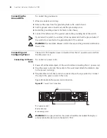
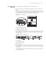
Connecting Module
Cables
This section describes how to connect electrical and optical cables.
Connecting Electrical Port Cables
The 48-port 10/100BASE-T module and 8-port 10/100/1000BASE-T module
require a RJ-45 connector and category-5 twisted pair cable. See “Electrical Port
Connector” on page 68 for an illustration of the RJ-45 connector and MDI/MDI-X
pinout details.
Use the following steps to connect the port:
1
Plug one end of the straight-through cable into the Ethernet RJ-45 port of the
switch.
2
Plug the other end of the straight-through cable into the RJ-45 port of the hub or
LAN Switch.
Ports on 48-port 10/100BASE-T and 8-port 10/100/1000BASE-T modules support
MDI/MDI-X auto-sensing.
Connecting Optical Fiber Cables
The following modules require fiber optic cables:
■
24-port 100BASE-FX MMF FE module
■
20-port 1000BASE-X-SFP module
■
1000BASE-SX-MM, 1000BASE-LX-SM-IR, and 1000BASE-LX-SM optional GBIC
modules for the 4-port 1000BASE-X-GBIC submodule
When connecting optical fiber cables, use the fiber connectors that are
appropriate for the optical port type of the peer equipment that is connected to
the local network port module. See “Optical Fiber Cable Connectors” on page 69
for illustrations of the fiber optic cable connectors.
Single-mode optical fiber cable is used for external connections of the single-mode
optical port. Multi-mode optical fiber cable is used for external connections of the
multi-mode optical port.
Before connecting the optical fiber cable, make sure the type of the connector and
the optical fiber cable are consistent with the optical port type.
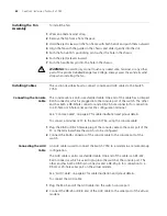
WARNING:
When a connector is not inserted in the optical port or when its
dustproof cover is open, invisible radiation can escape from the optical port. Do
not stare into the optical port directly. Cover the optical port if there is no
connector plugged in.
SC fiber connector
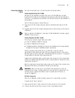
The 8-port 1000BASE-X GBIC module requires an SC optical fiber connector.
To attach the SC fiber connector:
1
Plug one end of the SC fiber connector into the optical port in the module.
2
Connect the other end of the connector to the corresponding device.
Содержание 3C16895
Страница 6: ......
Страница 44: ...44 CHAPTER 2 INSTALLING THE SWITCH 7750...
Страница 74: ...74 APPENDIX B OBTAINING SUPPORT FOR YOUR SWITCH...


