background image

15

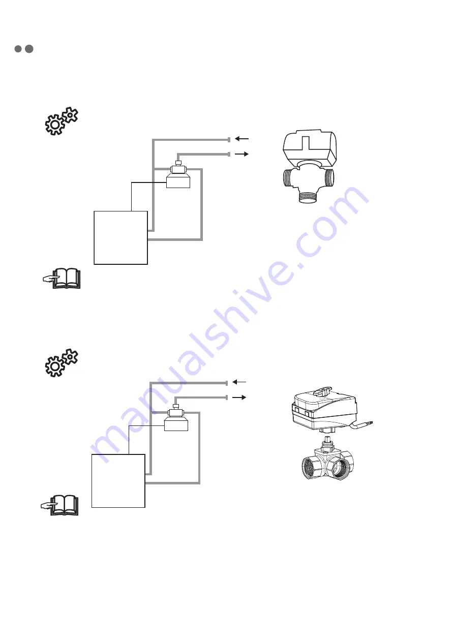
6.2-2 Regulating the water coil with a ZV-3 or RT zone valve (Air curtains with water coil and 

COMFORT control module: VCS-R2-CO-V-xx)

                        Zone valve ZV-3 is an required accessorie for control module VCS-R2-CO-V-xx

• 

Detailed description of water coil regulation by zone valve (ZV-3), including it´s connection, refer the 

instruction manual for zone valve ZV-3.


Zone valve RT is an required accessorie for control module VCS-R2-CO-V-xx

• 

Detailed description of water coil regulation by zone valve (RT), including it´s connection, refer the 

instruction manual for zone valve RT.

AB

A

B

ZV-3

AB

A

B

ZV-3

VCF-x-xxx-V(W)-...

+

VCS-R2-CO-V-xx

6. INSTALLATION

www.first.si

Let Firšt be your first choice.

www.first.si

FIRŠT d.o.o.


Koroška cesta 56


SI-3320 Velenje 

SLOVENIA 

phone:  

+386 3 898 35 00


fax: 

+386 3 898 35 35


email:   [email protected]


web:  

www.first.si

A C T U A T O R S

V A L V E S

H E A T I N G   C O N T R O L L E R S

Let Firšt be your first choice.

S9000-DIV

DIVERTING/CHANGEOVER UNIT 

3-way rotary brass valves with electric actuator S9000-DIV and Clip system

A

A

A

B

B

B

 FDV 231C                    FDV 232C 

  FDV 233C

internal threads                            external threads 

     compression fittings 

S9000-DIV 231C

,


internal threads

  Code   Type                                                           DN      Kvs         Voltage          Rotation time     Control    Connection       A         B        C         Weight [kg]        Price (€)

 14230   S9iN0-DIV 231C DN15 Rp ½"            15       3        230 V~ 50 Hz     12s/90°            2P          Rp ½"             36       72      115           0,89
 14231   S9iN0-DIV 231C DN20 Rp ¾"            20       7        230 V~ 50 Hz     12s/90°            2P          Rp ¾"             36       72      115           0,96
 14232   S9iN0-DIV 231C DN25 Rp 1"             25      11       230 V~ 50 Hz     


12s/90°           2P          Rp 1"              41       82      115           0,99

 14233   S9iN0-DIV 231C DN32 Rp 1 ¼"         32      15      


230 V~ 50 Hz     


12s/90°           2P         Rp 1 ¼"          47       94      118           1,31

S9000-DIV 232C

, external threads

  Code   Type                                                           DN     Kvs        Voltage          Rotation time     Control    Connection       A         B        C        Weight [kg]        Price (€)

 14238   S9iN0-DIV 232C DN15 G ¾"              15  


3       230 V~ 50 Hz     12s/90°            2P          G ¾"               36       72      


115           0,87

 14239   S9iN0-DIV 232C DN20 G 1"               20  


7        230 V~ 50 Hz     12s/90°            2P          G 1"                36       72      


115           0,91

 14240   S9iN0-DIV 232C DN25 G 1 ¼"           25     


11       230 V~ 50 Hz     12s/90°            2P          G 1 ¼"            41      


82      


115           1,06


*

14241  S9iN0-DIV 232C DN32 G 1 ½"           32     


15      230 V~ 50 Hz     12s/90°           


2P          G 1 ½"            47      


94      


118           1,27

S9000-DIV 233C

,


compression fittings

  Code   Type                                                           DN     Kvs        Voltage          Rotation time     Control    Connection       A         B        C        Weight [kg]        Price (€)

 14244   S9iN0-DIV 233C DN20 C22mm          20      7        


230 V~ 50 Hz     12s/90°           


2P        CPF 22mm       36       72      115           0,95

 14245   S9iN0-DIV 233C DN25 C28mm          25     11       


230 V~ 50 Hz     12s/90°          


2P      


CPF 28mm       41       82      115           1,08

* Units are available on special request.

S9000-DIV / FIRŠT

 d.o.o. / Copyright 2015

Installation examples

Features and options


Auxiliary switch:

 one potential free auxiliary switch in the end position 

of the actuator is available as an option.


Molex connector: 

optional Molex connector (IP40) and optional 

specially sealed Molex cable (IP44).


Supply voltage: 

230 VAC, 50 Hz, 24 VAC, 50 Hz.


Manual control handle: 

with or without manual control handle.


Solar/cooling adapter:

 Heat barrier for protection of the actuator in 

solar or cooling systems.


Diverting application         Changeover application

In accordance with PED, LVD, RoHS2, EMC.

109

C

RT

Содержание FINESSE

Страница 1: ...INSTALLATION EN FINESSE ...

Страница 2: ...entation without prior notice Save this user manual for further use The instructions in this manual are a part of the product Statement of compliance You will find the details at the www 2vv cz website M A N Z Ý V L O B M Y S VÝSTRAHA Upozornění varování NEPŘEHLÉDNĚTE Důležité instrukce BUDETE POTŘEBOVAT POZNÁMKA Praktické tipy a informace TECHNICKÉ INFORMACE Podrobnější technické informace ODKAZY...

Страница 3: ...your claim may not be valid later Checktoseeifitisthesameproductyouorde rot If there are any discrepancies do not un pack the curtain and immediately report the defect to the supplier After unpacking check to see if the curtain and other parts are in order If you have any doubts contact the supplier Never install a damaged air curtain If you do not unpack the curtain immediately after delivery it ...

Страница 4: ...4 3 MAIN PARTS 1 2 3 3 4 5 5 6 Suspension holders Electric heater water without Power supply cable plug Power supply connectors and fusse location Control modul socket Outlet grid 1 2 6 4 ...

Страница 5: ... 304 1 25 596 5 638 5 250 A B C Type Spacing of installation holes A mm Length B mm Length of cover C mm VCF x 100 x 1085 1124 1 1166 1 VCF x 150 x 1585 1624 1 1666 1 VCF x 200 x 2085 2124 1 2166 1 VCF x 250 x 2465 2504 1 2546 1 ...

Страница 6: ... 2 41 VCF B 150 V AC 3100 59 6 38 77 230 3 3 56 VCF B 200 V AC 4280 61 52 61 230 4 3 73 VCF B 250 V AC 5140 62 5 62 29 230 5 4 87 VCF B 100 S AC 2270 58 3 230 2 2 37 5 VCF B 150 S AC 3280 60 2 230 3 4 51 VCF B 200 S AC 4400 61 5 230 4 2 66 VCF B 250 S AC 5460 62 7 230 5 4 80 VCF C 100 E AC 5 2960 61 2 9 6 400 17 9 230 4 0 44 VCF C 150 E AC 4080 62 7 14 7 400 27 2 230 5 2 60 VCF C 200 E AC 5180 64 ...

Страница 7: ...B 150 E EC 2710 60 8 15 400 24 9 230 3 2 48 5 VCFI4B 200 E EC 3620 62 2 19 400 31 7 230 4 3 63 VCFI4B 250 E EC 4520 63 4 24 5 400 40 7 230 5 3 75 VCFI4B 100 V EC 1700 57 5 19 1 230 2 2 37 VCFI4B 150 V EC 2550 59 3 29 7 230 3 2 50 VCFI4B 200 V EC 3400 60 5 39 5 230 4 3 65 VCFI4B 250 V EC 4250 61 8 48 4 230 5 3 77 VCFI4B 100 S EC 1850 58 8 230 2 2 33 5 VCFI4B 150 S EC 2760 60 8 230 3 2 45 VCFI4B 200...

Страница 8: ... AC 3900 44 57 52 3 0 53 35 1 VCF C 200 V AC 5070 56 99 51 7 0 68 27 VCF C 250 V AC 5860 62 29 54 4 0 74 17 8 Air curtains with a water coil for a water temperature gradient of 80º 60 C and at an intake air tempe rature of 18 C Type Air flow m3 h Heat output kW Outlet temperature C Water flow l s Pressure loss kPa VCF B 100 V AC 2140 20 28 46 4 0 24 8 8 VCF B 150 V AC 3100 31 78 48 8 0 38 20 8 VCF...

Страница 9: ...C 150 V AC 3900 28 87 40 2 0 34 17 2 VCF C 200 V AC 5070 36 88 39 8 0 44 13 8 VCF C 250 V AC 5860 40 28 41 5 0 48 9 7 Air curtains with a water coil for a water temperature gradient of 60º 40 C and at an intake air temperature of 18 C Type Air flow m3 h Heat output kW Outlet temperature C Water flow l s Pressure loss kPa VCF B 100 V AC 2140 11 83 34 6 0 14 4 1 VCF B 150 V AC 3100 18 59 36 0 22 8 8...

Страница 10: ...F C 250 W 5260 29 81 35 0 6 16 3 Air curtains with a water coil for a water temperature gradient of 35 25 C and at an intake air temperature of 18 C Type Air flow m3 h Heat output kW Outlet temperature C Water flow l s Pressure loss kPa VCF C 100 W 2530 9 4 29 2 0 2 8 6 VCF C 150 W 3500 13 3 29 4 0 3 8 2 VCF C 200 W 4670 18 29 6 0 3 8 4 VCF C 250 W 5260 21 30 0 4 9 4 The warm water temperature coi...

Страница 11: ...ances for flammable materials and safe use of air curtain has to be kept The installed position of the air curtain can be chosen to accommodate the service hood It must be operated in dry coverot indoor spaces with an ambient temperature between 5 C and 40 C and relative humidity up to 80 Theaircurtainisnotintendedformovingairthatcontainscombustibleorexplosivemixtures chemi cal fumes coarse dust s...

Страница 12: ...2520 620 Air curtain is fixed to the ceiling by 4 threaded rods which are not included delivery It is necessary to ensure proper in the supply at the site according to the exact type of use of the air curtain and based on its electric parameters When using water heated air curtain please ensure connection of the flow and return pipes It is necessary to cut or otherwise make a hole according to the...

Страница 13: ...d the air curtain on the threaded bars and ensure that the suspension will not come loose In consideration of the air curtain weight into account it is necessary to use either a suitable lifting device forklift etc or use two additional individuals to support it as long as it is not securely faste ned Suspension has to carry the weight of the air curtain 6 INSTALLATION 31 9 15 5 95 5 175 5 255 5 3...

Страница 14: ...e is 1 6 MPa We recommend installing a stop valve on the intake and outlet of the heater to allow the water supply to be shut off 6 2 1 Regulating the water coil with a thermostatic valve TV1 1 Air curtains with water coil and BASIC control module VCS R2 BA V xx Thermostatic valveTV1 1 is an required accessorie for control moduleVCS R2 BA V xx Detailed description of water coil regulation by therm...

Страница 15: ... 231C FDV 232C FDV 233C internal threads external threads compression fittings S9000 DIV 231C internal threads Code Type DN Kvs Voltage Rotation time Control Connection A B C Weight kg Price 14230 S9iN0 DIV 231C DN15 Rp 15 3 230 V 50 Hz 12s 90 2P Rp 36 72 115 0 89 14231 S9iN0 DIV 231C DN20 Rp 20 7 230 V 50 Hz 12s 90 2P Rp 36 72 115 0 96 14232 S9iN0 DIV 231C DN25 Rp 1 25 11 230 V 50 Hz 12s 90 2P Rp...

Страница 16: ...Zone valve ZV 3 24V is an required accessorie for control moduleVCS R2 SU V xx Supply 24 V 50 60 Hz 24V external source not included control tension 0 10V VCF x xxx V W VCS R2 SU V xx Detailed description of water coil regulation by zone valve ZV 3 24V including it s connection refer the instruction manual for zone valve ZV 3 24V AB A B ZV 3 ZV 3 24V ...

Страница 17: ...ected to any control system other than the original one the regulation and me asurement components must be connected by the company that supplied the system Theelectricalcontractordefinestheminimumsizeofthefeedcableaccordingtothestandardsappli cable at the place of installation the location for installing the cable the surrounding conditions and the curtain s technical parameters Special attention...

Страница 18: ...r curtains are equipped with a fuse with T characteristic slow blow This safety fuse pRo tects the electronic panel and fans It is located under the service cover next to the main power supply connectors 6 5 CONTROL MODULES Air curtains FINESSE are produced with universal connection interface Air curtains FINESSE can be controlled by one of following control modules BASIC COMFORT SUPERIOR Control ...

Страница 19: ...19 6 6 INSERT CONTROL MODULETOTHE AIR CURTAIN 6 INSTALLATION 2 1 ...

Страница 20: ...20 6 INSTALLATION Connection to the regulation control panel and accessories 3 4 a b c d e Connect the remote control and accesso ries to the terminals on the electronic board ...

Страница 21: ...21 6 INSTALLATION 6 7 EXIT SIGN Exit sign marking of emergency exit For all types of VCS4x air curtains Not included in delivery 6 8 COVERINGTHE AIR CURTAIN EXIT EXIT ...

Страница 22: ...ll connected The unit is properly covered The control panel is properly connected Duringthecommissioning checktheproperfunctionoftheunit fans heating Checktheotherpossi ble settings and functions according to the user manual of each regulator 7 1 SET AIR FLOW DIRECTION This is set by tilting the air curtain s fan louvers in the desirot direction 7 INITIAL START UP ...

Страница 23: ...ng time used accessories installation location installation condition including electrical detailed description of the problem and the steps that you have taken for its removal Warranty and post warranty service is performed by the manufacturer supplier or authorized service organization When ordering service intervention it is necessary to describe the defect product type designation indicated on...

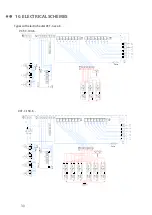
Страница 24: ...24 10 ELECTRICAL SCHEMES Types without heating VCF B xxx S VCF B 100 VCF B 150 VCF B 200 VCF B 250 Fuse Fuse ...

Страница 25: ...25 Types with water coilVCF B xxx V W 10 ELECTRICAL SCHEMES Fuse VCF B 100 VCF B 150 VCF B 200 Fuse VCF B 250 ZV 3 RT ZV 3 RT ...

Страница 26: ...26 Types with electric heaterVCF B xxx E VCF B 100 E VCF B 150 E 10 ELECTRICAL SCHEMES Fuse Fuse Fuse ...

Страница 27: ...27 VCF B 200 E VCF B 250 E 10 ELECTRICAL SCHEMES Fuse Fuse ...

Страница 28: ...28 VCF C 100 S VCF C S 10 ELECTRICAL SCHEMES Types without heating VCF C S Fuse Fuse VCF C 150 VCF C 200 VCF C 250 ...

Страница 29: ...29 10 ELECTRICAL SCHEMES Types with water coilVCF C xxx V W VCF C 100 V W VCF C V W VCF C 100 Fuse Fuse VCF C 150 VCF C 200 VCF C 250 ...

Страница 30: ...30 10 ELECTRICAL SCHEMES VCF C 100 E VCF C 150 E Types with electric heaterVCF C xxx E Fuse Fuse ...

Страница 31: ...31 VCF C 200 E VCF C 250 E 10 ELECTRICAL SCHEMES Fuse Fuse ...

Страница 32: ...CFI4B B100 S EC VCFI4B B100 EC VCFI4B B150 VCFI4B B200 VCFI4B B250 Nýzev VCSF4 B 250 V EC Verze 1 Firma 2VV Kreslil KrýtkŤ 5 4 2 1 3 PE N N L L PE PLÁ 0 10V 6 7 8 2 3 4 5 1 Temperature sensor inlet 1 1 M 1 M 1 M 1 M 1 M L N N L N L N L N L RPM PWM GND RPM RPM RPM RPM 2 3 4 5 GND PWM GND PWM GND PWM GND PWM 6 7 8 2 3 4 5 1 PE PE PE PE PE MUT V3 M zdroj 24 N L GND N PE Čslo 3 010 S08574 Datum 2 8 20...

Страница 33: ...dí 10V VCFI4B B100 E EC VCFI4B B150 E EC 1 2 3 4 5 6 8 7 2x 1250W 230V Th1 TH 10 80 C R1 R1 9 8 7 2x 1250W 230V 2x 1250W 230V 2x 1250W 230V 2x 1250W 230V 2x 1250W 230V Th1 Th1 TH 10 80 C TH 10 80 C TH 10 80 C Th1 R6 R6 R5 R5 R4 R4 R3 R3 Th1 TH 10 80 C Th1 TH 10 80 C R2 R2 THERMOSTAT Nízev VCSF4 B 150 E EC Verze 1 Firma 2VV Kreslil Krítkž N N PE PE L2 L1 L2 L1 L3 L3 CYKY 5Cx10 0 400V 50Hz 2 1 4 6 8...

Страница 34: ...B250 E EC Nízev VCSF4 B 250 E EC Verze 1 Firma 2VV Kreslil Krítkž Datum 2 8 2017 9 2x 1580W 230V R7 R7 R6 2x 1250W 230V R6 R5 R5 2x 1580W 230V 6 5 4 R4 R4 2x 1580W 230V 3 2 1 R8 2x 1250W 230V R8 R9 R9 2x 1250W 230V 9 Th1 Th1 TH 10 80 C TH 10 80 C TH 10 80 C Th1 8 7 Th1 TH 10 80 C TH 10 80 C TH 10 80 C Th1 Th1 7 8 2x 1250W 230V R2 R2 R3 R1 R1 2x 1250W 230V 2x 1250W 230V R3 Th1 TH 10 80 C TH 10 80 C...

Страница 35: ... the Manualfortheappropriateregulator In case of any doubt or query do not hesitate to contact our sales or technical support departments CONTACT Address 2VV s r o Poděbradská 289 530 09 Pardubice Česká republika Internet http www 2vv cz 11 CONCLUSION ...

Отзывы: