background image

Installation manual 2N® IP Force


57

 /  

118

Device Restart

Press the RESET button shortly (< 1 s) to restart the system without changing 
configuration.


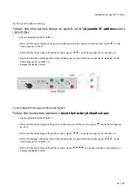
Factory Default Resetting (PCB version 555v3 and higher)

For resetting device to default settings press and hold SW1 button. Wait for 
the  first  sound  signalization  and  then  release  the  button.  If  you  press  the 
button  for  short  time  device  will  reboot  only.  SW1  button  is  available  in 
devices  with  PCB  version  555v3  and  higher.  For  devices  with  PCB  version 
555v2 see procedure below.

Caution

In case of resetting the factory default settings on a device with a version of firmware 2.18 or higher 
it is necessary to reprogram the 

2N

®

 Security Relay 

using the instructions from section 

2.4

.

Note

The time interval between the short press of RESET and reconnection after restart is 25–50 s for 

2N

®

 IP Force 

depending on the HW version.

Caution

Содержание IP Force 9151101W

Страница 1: ...Installation manual 2N IP Force v 2 18 www 2n com...

Страница 2: ...2 2 Mechanical Installation 2 3 Electric Installation 2 3 1 Overvoltage Protection 2 4 Extending Module Connection 2 5 Button Tags 3 Function and Use 3 1 Configuration 3 2 Control 3 3 Maintenance 3 4...

Страница 3: ...g AEC system the product provides mutual audibility even of persons talking at the same time under normal conditions 2N IP Force can be equipped with a colour wide angle camera which displays the call...

Страница 4: ...ncelling Integrated colour camera with wide angle lens Optional dial buttons including name tags and backlight Optional numerical keypad with backlight Integrated electronic lock switches with wide se...

Страница 5: ...nstallation manual 2N IP Force 5 118 Basic Units One Button 2N Part No 9151101W Axis Part No 01336 001 1 button control of two electric locks additional switch connection option 10 W loudspeaker IP69K...

Страница 6: ...camera 10 W loudspeaker IP69K extra robust version control of two electric locks additional switch connection option 2N Part No 9151101CHW Axis Part No 01337 001 IP69K 1 button HD camera control of tw...

Страница 7: ...s possibility of connecting card reader control of two electric locks additional switch connection option 10 W loudspeaker IP69K 2N Part No 9151101CRP W 1 button pictograms with camera possibility of...

Страница 8: ...ograms with HD camera possibility of connecting card reader control of two electric locks additional switch connection option 10 W loudspeaker IP69K night vision 2N Part No 9151101KW Axis Part No 0133...

Страница 9: ...dspeaker IP69K 1 button keypad camera control of two electric locks additional switch connection option 2N Part No 9151101CHK W Axis Part No 01339 001 10 W loudspeaker IP69K 1 button keypad HD camera...

Страница 10: ...amera possibility of connecting card reader control of two electric locks additional switch connection option 10 W loudspeaker IP69K night vision 2N Part No 9151102CRW 2 buttons camera possibility of...

Страница 11: ...2 buttons card reader connection option control of two electric locks additional switch connection option 10 W loudspeaker IP69K 2N Part No 9151102 X1 10W loudspeaker IP69K 2 buttons with INFO and SO...

Страница 12: ...51104W Axis Part No 01342 001 10 W loudspeaker IP69K 4 buttons control of two electric locks additional switch connection option 2N Part No 9151104CW 10 W loudspeaker IP69K 4 buttons camera control of...

Страница 13: ...option night vision 2N IP Force is designed for outdoor applications and requires no additional roof W including Part Nos are intended for WAP pressure cleaning and extremely noisy environments such a...

Страница 14: ...Installation manual 2N IP Force 14 118 Flush Mounting Box frame included with basic unit 2N Part No 9151001 Axis Part No 01348 001 Brick flush mounting box Dimension 132 x 223 x 83 mm...

Страница 15: ...N Part No 9151002 Axis Part No 01349 001 Plasterboard flush mounting box Dimension 237 x 129 x 70 mm Hole 237 x 118 mm Mounting Accessories 2N Part No 9151005 Axis Part No 01351 001 Gooseneck stand He...

Страница 16: ...tallation manual 2N IP Force 16 118 2N Part No 9151007 Axis Part No 01550 001 Gooseneck stand double Height 115 cm 45 and 203 cm 80 2N Part No 9151006 Axis Part No 01352 001 Installation adapter US on...

Страница 17: ...es Part Numbers 2N Part No 91378375 Axis Part No 01668 001 2N Part No 91378376 Axis Part No 01670 001 2N Indoor Touch 2 0 black WiFi version latter Part No 2N Indoor Touch 2 0 an elegant internal touc...

Страница 18: ...001 2N Part No 91378376WH Axis Part No 01671 001 2N Indoor Touch 2 0 white WiFi version latter Part No 2N Indoor Touch 2 0 an elegant internal touch panel is suitable for all 2N IP intercoms On the p...

Страница 19: ...GXV3240 VoIP video telephone GXV3240 is the successor to the popular GXV3140 model which allows for comfortable video calls in the IP network Touchscreen and keyboard control 2N Part No 91378358 Axis...

Страница 20: ...t momentum electric pulse is sufficient for unlocking the door into the OPEN position After the door is passed through the lock is in the CLOSED position again 2N Part No 932091E BEFO 11211MB with mec...

Страница 21: ...DC The failsafe lock is closed when electricity is switched on When electricity is interrupted the lock is opened 2N Part No 932062E BEFO 321211 fail safe door signalling 12 V 170 mA The failsafe loc...

Страница 22: ...etor with EU cable PoE injector with US cable For intercom power supply via an Ethernet cable where no PoE switch is available 2N Part No 91341481E Stabilised 12 V 2 A power supply needs to be used wh...

Страница 23: ...tch for 2N IP Force front panel opening signalling 2N Part No 9151011 Axis Part No 01344 001 Internal RFID card reader 125 kHz for installation in 2N IP Force intercoms Allows the use of EM4xxx cards...

Страница 24: ...mber is read ISO14443A Mifare DESFire PicoPass HID iClass FeliCa ST SR IX 2N Mobile Key 2N Part No 9151031S Axis Part No 01730 001 Internal secured RFID card reader 13 56 MHz NFC HCE Ready for 2N IP F...

Страница 25: ...2N Security Relay A handy add on that significantly enhances door entry security as it prevents tampering with the intercom and forced opening of the lock To be installed between intercom and lock pow...

Страница 26: ...ands sent by 2N IP intercom which can thus control devices on unlimited distance 2N Part No 9137411E Axis Part No 01398 001 External IP Relay 4 outputs PoE Standalone IP device which can be controlled...

Страница 27: ...N Part No 9134173 Axis Part No 01384 001 Mifare Classic 1k RFID card 13 56 MHz 2N Part No 9159050 Axis Part No 01391 001 2N Induction Loop An induction loop transmits sound wirelessly from the 2N IP i...

Страница 28: ...59014US Axis Part No 01404 001 2N 2Wire set of 2 adaptors and power source for EU US UK The 2N 2Wire converter allows you to use the existing wiring 2 wires from your original doorbell or door interco...

Страница 29: ...table for Internal RFID card reader Set for installation on a door enabling the status of door opening to be ascertained Used when the intercom is used for door protection to detect when the door is n...

Страница 30: ...from both sides of the door IP68 cover also suitable for exteriors Reads Mifare cards 2N Part No 9154004 Axis part No 01479 001 Water proof metal button Suitable for Internal RFID card reader 2N Part...

Страница 31: ...version 4 3 2N Mobile Key app required EMarine 2N Part No 9137424E Axis part No 01527 001 Ext secured RFID Reader 13 56 MHz 125 kHz NFC HCE USB interface External secured RFID card reader for connect...

Страница 32: ...5 Enhanced Audio 2N Part No 9137906 Enhanced Video 2N Part No 9137907 Enhanced Integration 2N Part No 9137908 Enhanced Security 2N Part No 9137909 Gold 2N Part No 9137910 Axis Part No 01381 001 Inform...

Страница 33: ...rticular advice please contact your local distributor of 2N products Tip FAQ Induction loop How to connect it with 2N IP intercoms Safety Always abide by this information to prevent persons from injur...

Страница 34: ...wrench Bushings enclosed 1x big two hole sealed bushing with nut 1x spare sealing for big bushing for a thick cable one hole 1x big blank with nut 1x small bushing with nut 1x bushing plug big size 2...

Страница 35: ...of the wall Stainless steel screws are used for the 2N IP Force assembly Other screws than stainless steel ones corrode soon and may aesthetically deteriorate the surrounding environment Having remove...

Страница 36: ...orce 36 118 F l u s h M o u n ti n g C l a s si c B ri c k s Warning Be sure keep strictly the hole dimensions while mounting the device into classic bricks without the flush mounting box as shown in...

Страница 37: ...Installation manual 2N IP Force 37 118 What You Need The brick flush mounting box Part No 9151001 Hole 132 x 223 x 83 mm...

Страница 38: ...Installation manual 2N IP Force 38 118 If y o u u s e t h e b ri c k fl u s h m o u n ti n g b o x f ol lo w t h e...

Страница 39: ...the rest under the intercom bottom Insert the supplied screws in the side mounting holes making sure that they penetrate into the flush mounting box nuts Tighten all the screws properly Tip The screw...

Страница 40: ...ions included therein Caution The hole depth depends on the insulation layer thickness If the insulation layer is rather thick you may need longer screws If there are hollow bricks under the insulatio...

Страница 41: ...ounting box Part No 9151001 Hole 132 x 223 x 83 mm Suppose you intend to install your 2N IP Force unit into a wall made of hollow bricks Note that the external side of the bricks gets damaged by cutti...

Страница 42: ...Force 42 118 Wall Mounting What You Need Just your 2N IP Force unit Wall surface mounting is used where flush mounting is inapplicable in concrete and steel structures entry barrier columns etc The f...

Страница 43: ...the unit as a reserve Insert the plugs in the unused bushings and tighten the bushing nuts carefully Do not complete mounting until you have finished electrical installation Where cables lead along th...

Страница 44: ...ording to the type of surface Use a cable bushing for the 2N IP Force cable fee out Use of Cable Bushings The cable bushings included in the 2N IP Force delivery are designed for the following cables...

Страница 45: ...ompletely 2 Remove the sealing including the cover from the bushing Cut either of the components as shown in the figures 3 Put the bushing nut on the cable and insert the sealing 4 Replace the cover o...

Страница 46: ...the cable connector though the bushing body into the intercom and clip it into the motherboard connector 6 Move the sealing including the cover along the cable as far as the bushing body or add a plu...

Страница 47: ...3 and higher Factory Default Resetting PCB version 555v2 Grounding Mounting Completion Available Switches PCB Connectors Picture shows the lay out of connectors on the 2N IP Force printed circuit boar...

Страница 48: ...X16 Right hand microphone X17 Relay NO and NC contact max 30 V 1 A AC DC Used for connection of non critical devices only lights e g X18 Switched output 9 up to 13 V DC depending on power supply PoE 9...

Страница 49: ...Installation manual 2N IP Force 49 118 2N IP Force Connectors PCB Version 555v3...

Страница 50: ...Installation manual 2N IP Force 50 118 2N IP Force Connectors PCB Version 555v4...

Страница 51: ...Installation manual 2N IP Force 51 118 2N IP Force Connectors PCB Version 555v5 Tip Output wiring diagram for Relay terminals...

Страница 52: ...le of category Cat 5e or higher The system is equipped with the Auto MDIX function and so both the straight and crossed cable versions can be used Wiring diagram for the controlled device s electric c...

Страница 53: ...ments If your LAN in incompatible insert the PoE injector Part No 91378100E US between 2N IP Force and the nearest network element Electric Lock Connection 2N IP Force is equipped with an electrically...

Страница 54: ...RESET button Wait until the red and green LEDs go on simultaneously on the device and the acoustic signal can be heard approx 15 35 s Release the RESET button The device automatically announces the c...

Страница 55: ...d approx 15 35 s Wait until the red LED goes off and the acoustic signal can be heard approx for another 3 s Release the RESET button The following network parameters will be set after restart IP addr...

Страница 56: ...e acoustic signal can be heard approx for another 3 s Release the RESET button Factory Reset PCB version 555v5 and higher Follow the instructions below to reset the factory default values Press and ho...

Страница 57: ...ou press the button for short time device will reboot only SW1 button is available in devices with PCB version 555v3 and higher For devices with PCB version 555v2 see procedure below Caution In case o...

Страница 58: ...e Normal operation position Reconnect the power supply The device will be reset to factory default Normal operation Default setup Configuration jumpers X6 PCB version 555v2 Grounding We recommend to g...

Страница 59: ...e for the board if you are installing a four button board Tighten the four screws thoroughly with the wrench enclosed Torx 20 to make the panel fit tightly to the metal chassis Available Switches Caut...

Страница 60: ...E 9 V adaptor power supply voltage minus 1 V max 600 mA Additional Switch Part No 9151010 Relay 2 Passive relay switch NO and NC contacts up to 30 V 1 A AC DC Used for connection of non critical devic...

Страница 61: ...ly voltage minus 1 V max 600 mA Only one module marked by can be used 2 3 1 Overvoltage Protection Recommendations for Additional Overvoltage Protection Installation If running a outside a building b...

Страница 62: ...ere the wires leave the building OVP overvoltage protection 2 4 Extending Module Connection 2N IP Force allows the following extending modules to be connected Additional Switch Internal RFID Card Read...

Страница 63: ...to the 2N IP Force basic unit The purpose of the tamper switch is to signal any unauthorised opening of the intercom to prevent a theft e g It is recommended to use the tamper switch Specifications v...

Страница 64: ...enclosed plastic support 6 onto the switch board bottom side Put the switch board 4 in the main board connector making sure that the screw hole is directly above the spacer According to your model If...

Страница 65: ...Installation manual 2N IP Force 65 118...

Страница 66: ...Installation manual 2N IP Force 66 118...

Страница 67: ...Installation manual 2N IP Force 67 118 Module settings Refer to the Configuration Manual for details Connection...

Страница 68: ...odule is intended for mounting into the 2N IP Force model 9151102CR 9151102R 9151101CRP and 9151101RP These models have an window which is necessary for antenna operation If the Internal RFID Card Rea...

Страница 69: ...P Force cover Relay output Switching contact 30 V 2 A AC DC Active output 12 V 700 mA transistor switched output Logical inputs Active mode requires external voltage JP2 jumper OFF UIN ON min 2 5 V UI...

Страница 70: ...Mounting guide...

Страница 71: ...upport 6 to the reader board from the bottom side Put the reader board 4 in the main board connector making sure that the mounting hole is directly above the spacer Screw in a remaining metal spacer 3...

Страница 72: ...Installation manual 2N IP Force 72 118...

Страница 73: ...Module setting...

Страница 74: ...outputs and reader Refer to the Automation manual for details of input red LED and tamper function and use Connection Wiegand Input Technical Parameters Current 5 mA Input resistance 680 Ohm Pulse len...

Страница 75: ...ted This module is intended for mounting into the 2N IP Force model 9151101RPW 9151101CRPW 9151101CHRPW 9151102RW 9151102CRW and 9151102CHRW These models have an window which is necessary for antenna...

Страница 76: ...D iClass FeliCa ST SR IX 2N Mobile Key RFID Reader 9151017 is compatible with cards only card serial number is read ISO14443A Mifare DESFire PicoPass HID iClass FeliCa ST SR IX 2N Mobile Key Relay out...

Страница 77: ...hort metal spacers enclosed to the reader Take a longer one 5 12 mm long Screw it into the free hole Plug an enclosed plastic support 6 to the reader board from the bottom side Put the reader board 4...

Страница 78: ...Installation manual 2N IP Force 78 118...

Страница 79: ...Installation manual 2N IP Force 79 118...

Страница 80: ...Module setting...

Страница 81: ...56 MHz The Internal RFID Card Reader 13 56 MHz Part No 9151031S 9151019 is used for reading RFID card Ids in the 13 56 MHz band NFC supported This module is intended for mounting into the 2N IP Force...

Страница 82: ...quency 13 56 MHz Minimum reading distance 30 mm above 2N IP Force cover RFID card reader 9151031S is compatible with cards optionally card serial number or PAC ID is read ISO14443A Mifare DESFire Pico...

Страница 83: ...Active output...

Страница 84: ...mount a button PCB 1 Don t disconnect its cable There will stay four spacers after the switch board removal Dismount the bottom right one There are two short metal spacers enclosed to the reader Take...

Страница 85: ...Installation manual 2N IP Force 85 118...

Страница 86: ...Installation manual 2N IP Force 86 118...

Страница 87: ...Module setting...

Страница 88: ...ation manual 2N IP Force 88 118 Refer to the Configuration Manual for details of Wiegand outputs and reader Refer to the Automation manual for details of input red LED and tamper function and use Conn...

Страница 89: ...Security Relay...

Страница 90: ...Relay includes a relay that can only be activated if the valid opening code is received from the intercom Specifications Passive switch NO and NC contacts up to 30 V 1 A AC DC Switched output Where t...

Страница 91: ...the output for 5 seconds Status signalling Green LED Red LED Status blinking off Operational mode on off Activated output blinking blinking Programming mode waiting for initialisation on blinking Err...

Страница 92: ...th separate power supply and interconnected via the Wiegand bus The 2N Wiegand Isolator protects the interconnected devices against communication errors and or damage Caution In case of resetting the...

Страница 93: ...wo wire Wiegand bus in one direction and a status LED signal in the other direction The module is power supplied from the Wiegand bus receiver side Specifications 2 wire WIEGAND IN 2 wire WIEGAND OUT...

Страница 94: ...Installation manual 2N IP Force 94 118 Connection...

Страница 95: ...d two wires for signal input the wires are connected into interconnection connector If you shorten the cable follow the colour marking Before wall mounting run the cable through the hole that you have...

Страница 96: ...ll power output 1 4 A sine wave signal 1 A pink noise signal Transition to standby w o signal 10 s Input level basic 100 mV 6 Vrms Input level increased 1 V 35 Vrms Input impedance 2 k parallel with 0...

Страница 97: ...plastic support 6 to the reader board from the bottom side Put the reader board 4 in the main board connector making sure that the mounting hole is directly above the spacer Screw in a remaining metal...

Страница 98: ...Installation manual 2N IP Force 98 118...

Страница 99: ...Installation manual 2N IP Force 99 118...

Страница 100: ...thus are not exposed to the risk of loss of components while replacing the tags Loosen the name plate screw using the wrench enclosed for example You can open the name plate window like a door without...

Страница 101: ...rce is switched into the dynamic IP address mode i e it obtains the IP address automatically if a properly set DHCP server is available in your LAN If no such DHCP server is available you can operate...

Страница 102: ...supply or disconnect and reconnect it if already connected Wait for the first acoustic signal Press buttons 1 1 1 2 2 3 sequentially The acoustic signal indicates mode switching Wait until the device...

Страница 103: ...t it if already connected Wait for the first acoustic signal Press buttons 2 1 1 2 2 3 sequentially The acoustic signal indicates mode switching Wait until the device is restarted automatically 2N IP...

Страница 104: ...mode switching Wait until the device is restarted automatically The static IP address mode will be switched into the dynamic IP address mode and vice versa upon restart 3 2 Control This subsection de...

Страница 105: ...can only be used for positions 1 to 4 The remaining positions can be retrieved via the numerical keypad if the Speed dial using digits function is enabled in configuration Procedure Enter the positio...

Страница 106: ...ion Activate deactivate a profile using the numerical keypad in order to define call routing to the telephone directory numbers more specifically Procedure Enter the numerical profile activating deact...

Страница 107: ...oid peroxide based cleaners Tip The 2N IP Force models of Part Nos 9151101W and 9151101CW may be cleaned with WAP high pressure washers Caution Always use the product for the purpose it was designed a...

Страница 108: ...control Adjustable with automatic adaptive mode Full duplex Yes AEC Speech transmission index STI 0 80 Audio stream Protocols RTP RTSP Codecs G 711 G 729 G 722 L16 16 kHz Camera SD Sensor 1 4 colour C...

Страница 109: ...lows in the Services Phone Video menu for calls and in the Services Streaming RTSP menu for streaming The set bandwidth represents the value that the codec has to approach on a long time average The d...

Страница 110: ...art No 9151016 only card serial number is read ISO IEC 14443A Mifare Classic 1k 4k DESFire EV1 Mini Plus S X Ultralight Ultralight C ISO IEC 14443B CEPAS HID iCLASS JIS X 6319 Felica Supported cards o...

Страница 111: ...luminium cast product front panel aluminium cast fiberglass FR4 91511xxxR Colour Not from RAL scheme matching equivalent would be 9004 glossy black Working temperature 40 C to 55 C Working relative hu...

Страница 112: ...Installation manual 2N IP Force 112 118 Flush mounting Plasterbo ard mounting Flush mounting with box...

Страница 113: ...equipment has been tested and found to comply with the limits for a Class B digital device pursuant to part 15 of the FCC Rules NOTE These limits are designed to provide reasonable protection against...

Страница 114: ...ges that the product device can achieve the guaranteed performance and full functionality pursuant to the manufacturer s instructions only if the latest product device version is used after having bee...

Страница 115: ...he product incurred as a result of misplacement incompetent installation and or undue operation and use of the product in contradiction herewith The manufacturer assumes no responsibility for any malf...

Страница 116: ...ed by the consumer in case the product is used and handled contrary to the said regulations and provisions The consumer shall at its own expense obtain software protection of the product The manufactu...

Страница 117: ...r give them back to the dealer or manufacturer for environmental friendly disposal The dealer or manufacturer shall take the product back free of charge and without requiring another purchase Make sur...

Страница 118: ...Installation manual 2N IP Force 118 118...

Отзывы: