


38
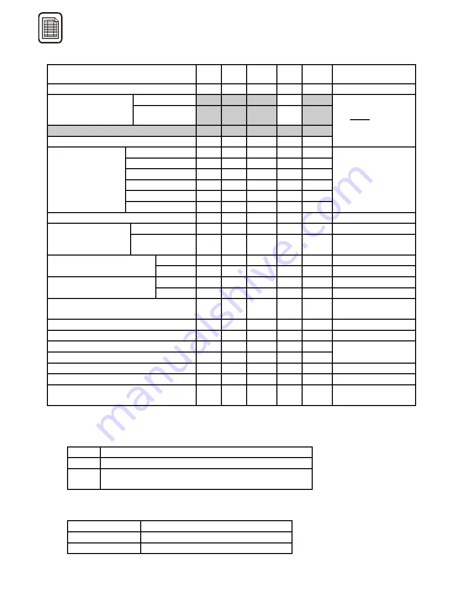
6.2. Line Interface Parameters
Parameter
Par.
No.
Min. Max. Def.
Your
choice
Remarks
Received dialling (DTMF / pulse)
201
0
1
0
0=DTMF, 1=pulse
Make min.,
204
-
-
20
-
Time parameters for
pulse dialling
receiver
Break min.,
205
-
-
30
-
Flash min.
206
10
2550 100
On-hook min.
207
10
2550 500
Time parameters
are
fixed
:
make 20 to 80 ms,
break 30 to 90 ms.
1st ring pulse
211
0
25500 1000
1st pause
212
0
25500 4000
2nd ring pulse
213
0
25500
0
2nd
pause
214 0 25500 0
3rd ring pulse
215
0
25500
0
Time parameters
for ringing
3rd
pause
216 0 25500 0
Step = 100 [ms]
Max time of ringing
224
0
255
0
[s], 0 = unlimited
Busy tone
225
1
255
30
Step = 1 [s]
Max off-hook time
without action
Power
down 226 0 255 60
0 = power down
disabled
Type 231
0 4 0
See
notes
below
Signalisation of begin
of GSM connection
Time
232
10
2000 100
Step = 10 [ms]
Type 233
0 4 0
See
notes
below
Signalisation of end
of GSM connection
Time
234
10
2000 100
Step = 10 [ms]
Frequency of signalisation pulse for
begin or end of connection
235 0 9 6
See
notes
below
Pseudo-tariff pulses transmit or no
241
0
1
0
0 = no, 1 = yes
Level of pulse transmitter
242
0
1
1
0 = low, 1 = high
Length of tariff pulse
243
10
1000 100
Min. pause between tariff pulses
244 10 1000 200
Step = 10 [ms]
Frequency of tariff pulses
245 0 9 6
See
notes
below
DISA dialling start time
251 100 25500 4000
Step = 100, [ms]
Dial switchboard operator number in
the course of DISA
252 0 1 0
0=no,
1=yes
Notes:
Parameters 231 and 233: Signalling of connection start or end:
0, 2, 3 None signalling
1
Current break for time specified by par. 232 or 234
4
Frequency impulse (typically 16 kHz), length see
parameter 232 or 234, frequency see parameter 235
Parameters 235 and 245: Frequency of tariff pulses or signalisation pulse for begin and end of
connection:
2 12
kHz
6 16
kHz
Other Reserved
Содержание ATEUS 501101E
Страница 2: ......
Страница 24: ...22 4 2 Description of GSM Gateway PCB Fig 7 Printed Circuit Board PCB of dual band GSM Gateway model 501101E ...
Страница 35: ...33 5 4 11 Remote Supervision Establishing Flow Chart ...
Страница 56: ......
Страница 57: ... 2002 2N TELEKOMUNIKACE a s Prague DR 972 v 1 33 ...


