2iB SC10 Скачать руководство пользователя страница 5


Tip: Generally it is better to have the pump start at a lower than a higher level, so select a Target Run Time which is lower or equal 
to what you expect to need. 

5.3


Start and Stop Modes 

The standard operating mode of the SC10 starts the pump based on the 
timer or the high float switch and stops when either the pump snores or 
the low float switch activates. 

Stop on Low Float Only / Disable Snore Stop:  Using DIP Switch 15 you can 
disable the pump stop based on the pump snoring so that the pump will 
only stop when the low float switch is reached.  This can be useful if you 
need the pump to stop at a specific level (that of the low float switch). 

Start on High Float Only / Disable the Timer Start:  Using DIP Switch 16 you can disable pump start based on the timer.  This 
means that the pump will only start based on the float switch.  This may be useful if you want the pump to start at a specific level 
(that of the high float switch).  This can be useful in hoppers or tanks. 

Float Switch Only Operation:  By switching both DIP Switches 15 and 16 ON the pump will start on the high float switch and stop 
on the low float switch.  (Timer start and Snore Stop will be disabled.)  This mode can be useful in hoppers or tanks.  This same 
operating mode can be used to start and stop the pump only on Start and Stop Pushbuttons. 

5.4


Alarm Relay Activation 

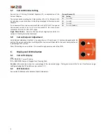
The SC10 has a single alarm output can be set to any combination of four 
functions  and  displayed  externally  with  a  fault  lamp  if  desired.  Ref  DIP 
Switches (6, 7, 8, 9) on front of SC10. 


CT Fault (diagnostic monitoring of CT) 


Sump Low  


Sump High 


Failed to Run (pump called to run no current detected) 

5.5


Stop / Low Level Switch Invert 

If a low level switch is used then the switch contact status needs to be set 
to normally open or closed. Ref DIP Switch (10) on front of SC10. 

Tip: If both the High and Low Level Switches are the same and their 
contacts close when the float switch is covered then you will need to set 
SW 10 to ON. 


5.6


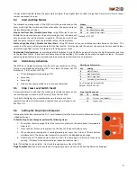
Setting the Stop Current Setpoint 

Pressing the Set button combination (

+

 simultaneously) sets the Stop Current to Measured Current 

+ Window Current 

To Set the Stop Current Setpoint perform the following steps: 

1.


Ensure that there is enough fluid in the sump or container so the pump doesn’t immediately 
draw in air 

2.


Press the Start button on the relay or on the front of the panel to start pump. 

3.


When the pump running and is  snoring (drawing air), press the 

Up and 

Down buttons 

simultaneously. The stop current setpoint is now set to the displayed percentage. 

4.


Allow  water  to  fill  above  pump  suction  and  start  the  pump  again  to  ensure  it  stops  when 
snoring.  If it doesn’t stop adjust setting or expand window current. 

Note: This settings is non-volatile.  It is stored through power-cycles of the SC10. 

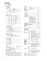
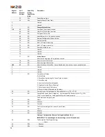
Single Phase Motors.  See also the note about single-phase motors in section 4.1 Snoring Detection Explained


Modes 

SW 

Setting 

15 

On: Disable Snore Stop 

16 

On: Disable Timer Start 

Default = Off, Off. 


Alarm Relay Activates for …


SW 

Setting 

AIN (CT) Fault 

Stop / Low Float 

Start / High Float 

Fail to Run (Low Current) 

On = Activates for this condition.  
Default= Off, Off, Off, Off


Stop / Low Float Invert 

SW 

10 

Setting 


Off 

Closed = Low (default) 


On 

Open = Low 


Содержание SC10

Страница 1: ...SC10 Single Pump Controller Installation and User Manual ...

Страница 2: ...ations To ensure accuracy and reliability screened twisted pair cable is to be used for connection of the Current Transducer for measuring the pump motor current 3 2 Remote Snoring Setup Controls for Operator Safety The Stop Current Setpoint can be set and adjusted using pushbuttons on the front of the pump starter control panel This enables the pump setup commissioning and setpoint adjustment to ...

Страница 3: ...elps clear the impellor and the suction strainer of debris reducing the chance of blockage and cavitation as well as increasing the flow rate and efficiency Start up of the SC10 The SC10 will normally start the pump 30 Seconds after start up The pump will run until a stop condition is reach snoring is detected or the stop low float is activated This pump start will not occur if the stop low float ...

Страница 4: ...CT In the circumstance that this isn t achievable there are four current range dip switch selections available 100 50 25 and 12 5 that increases the current percentage display providing full scale set point ranging setting i e if you have a 0 100 CT with a 50 Amp full load current the output is only 4mA to 12mA and the percentage of current displayed will only be 50 by switching dip switch 2 50 on...

Страница 5: ...6 7 8 9 on front of SC10 CT Fault diagnostic monitoring of CT Sump Low Sump High Failed to Run pump called to run no current detected 5 5 Stop Low Level Switch Invert If a low level switch is used then the switch contact status needs to be set to normally open or closed Ref DIP Switch 10 on front of SC10 Tip If both the High and Low Level Switches are the same and their contacts close when the flo...

Страница 6: ...int Adjustment An additional adjustment method is by using the up and down buttons independently By pushing the up or down button it will adjust the stop current threshold to the user s desired value as a percentage of CT current Note This settings is non volatile It is stored through power cycles of the SC10 6 Display and LED Indication 6 1 Current Display PA PAUSING Pump is Pausing CL CLEANING P...

Страница 7: ...nected to terminals 7 and 9 Ensure installed 4 20mA CT is correct range for installed load The pump stops although it is not snoring Ensure the inhibit low float input is not activated Stop current setpoint requires adjustment as it is set too high Adjust the stop current setpoint to a lower value If using the Set functionality during commissioning then adjust the Current Window to a lower value T...

Страница 8: ...ides 24VDC drive for CT Operating Temp 0 55 degrees Celsius Run Relay Contact Rating 5 A 48 VAC Resistive 1 5 A 48 VAC Pilot duty AC12 Alarm Contact Rating 5 A 48 VAC Resistive 1 5 A 48 VAC Pilot duty AC12 Dimensions W 106 5mm x H 90 50 mm x D 59mm Material PC ABS Mounting 35mm Din rail mounted Weight 300 g Certification EN 61000 6 3 2007 A1 AC FCC Part 15B 90 5mm ...

Страница 9: ...9 9 SC10 Connections See section 12 Reference for terminal identification Figure 1 SC10 Front Panel Figure 2 Connections ...

Страница 10: ...el PanelStart Remote Start Start Inputs Stop Inputs 5 Overload Reset Remote Set Point Up Remote Set Point Down Remote Threshold Set DIN Common O L 2 Emergency Stop 2 3 4 5 6 7 8 9 10 11 K1 Pump Run DIN 1 DIN 2 DIN 3 DIN 4 DIN 5 4 20mA 4 20mA 1 6 12 13 14 15 16 17 18 19 20 21 24 VAC A 24 VAC N 22 23 24 25 26 27 28 29 31 32 33 34 35 36 37 38 Ref Line 8 Ref Line 7 Ref Line 23 OL Ref Line 11 24 VAC A ...

Страница 11: ...nts in a few different ways Rated Current FLC Amps CT Rating Amps SC10 Current Range At Rated Current SC10 will Display Range DIP Switches SW 1 SW 2 An Example Optimal setup for an 8kW Pump Based on 11 1 above Option 1 As above 8 6 20 100 off off 30 30 of the range really is a bit low It would be best to adjust the range to increase the measurement Option 2 Change the Range Setting on the SC10 8 6...

Страница 12: ... Run Relay 4 5 Alarm Relay 6 7 Pump Current CT 4 20mA 8 9 Digital Inputs DIN Common 10 DIN 1 Start High Float 11 DIN 2 Stop Low Float 12 DIN 3 Up Pushbutton 13 DIN 4 Down Pushbutton 14 DIN 5 Set Pushbutton 15 DIN 8 Remote Config Mode 18 No Connection 19 27 Do not use AIN Loop Power 28 Modbus RTU RS485 A 29 B 30 Earth 31 No Connection 32 36 LED Indicators Power On Power is Present Flash Unit starti...

Страница 13: ...ses will be ignored Addressing Modbus addresses are indexed from 1 in the following table The address in the Modbus packet is 1 less than that address There is inconsistency between Modbus implementations about whether the addresses start from 0 or 1 so if you are not reading the value that you expect then consider reading the previous or next address Register Address Coil Discrete Address Read On...

Страница 14: ...p Fails to Run Pump Run Relay Active but no current was detected 6 Unused 7 Unused 8 Unused 9 RO Pump Control State 0 Initial State 1 Pump Pausing waiting for Pause Timer to expire 2 Pump Running 3 Low Level active Pump Stopped 4 High Level active Pump Running 5 Pump is pausing to flush pump 6 Pump is starting Pump not yet running 10 RO Pump Current Percentage with 1 decimal place e g 125 12 5 11 ...

Страница 15: ...llowing conditions are met 1 Redistributions of source code must retain the above copyright notice this list of conditions and the following disclaimer 2 Redistributions in binary form must reproduce the above copyright notice this list of conditions and the following disclaimer in the documentation and or other materials provided with the distribution 3 The name of the author may not be used to e...

Страница 16: ...B Pty Ltd 4 Barkala St Wellington Point QLD Australia Tel 61 7 3822 1005 Fax 61 7 3822 1008 support 2ib com au www 2ib com au 2018 2IB Pty Ltd All Rights Reserved SC10 Installation and User Manual V20180709 ...

Отзывы: