


4
Measured current when pump is snoring = 50% (50 Amps)
Current Window = 10% (10 Amps)
So, the Stop Current Setpoint is loaded with 50% + 10% = 60% (60 Amps)
The Current Window should be set to enable a Stop Current Setpoint to be set in between the Normal Running Current and the
Snoring Current.
If on the next pump run the measured snoring current is 55% (55Amps) then this will still be detected as snoring and the pump
will be stopped.
Single Phase Motors
Snore detection works identically on single-phase motors as it does on three-phase motors. Note however that on smaller motors
(single- or three-phase) the variation of current with load will be smaller which may make the setup more critical. In particular,
the Current Window setting may need to be smaller. Take a note of the current reading displayed on the SC10 and compare that
for normal operation and snoring and use this as a guide.
5.
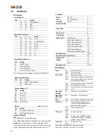
SC10 Set Up
The initial set up of the relay is done by setting these parameters:
1.
CT Current Range
2.
Pump Cycle Time
3.
Alarm Relay Activation Conditions
4.
Float Switch Contact Status
5.
Current Window %
6.
Stop Current Setpoint
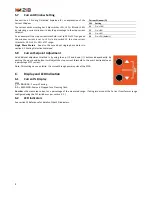
5.1
Current Range & Current Transformer Selection
The SC10 uses a 4-20mA Current Transformer (CT) to measure the motor current. The selected current transformer rated primary
current should be close to the full load current of the
connected load for optimal accuracy but should not
exceed it. Multiple turns of the motor phase wire could
be made through the CT to better match the motor rated
current to the CT.
In the circumstance that this isn’t achievable there are
four current range dip switch selections available 100%,
50%, 25% and 12.5% that increases the current percentage display providing full scale set point ranging setting
i.e. if you have a 0-100 CT with a 50 Amp full load current the output is
only 4mA to 12mA and the percentage of current displayed will only be
50% by switching dip switch 2 (50%) on it increases the display range
resolution to 100% providing full range selection.
Tip: For best accuracy, use (1) Multiple turns through the CT or (2)
Selectable range on the CT in preference to (3) Setting a lower range on the
SC10.
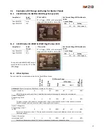
See also section 11 Examples of CT Range and Setup for Starter Panels.
Single Phase Motors. See also the note about single-phase motors in section 4.1 Snoring Detection Explained.
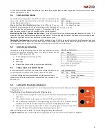
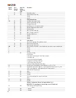
5.2
Pump Run Time Target
When the SC10 is first commissioned a pump run time target should be set,
the run time selection should reflect the time the sump or container is
currently taking to empty by the installed pump. The stop or pause time
duration is controlled by the SC10 controller and will vary based on run and
stop history and programmed adaptive control algorithm to attempt to
achieve the target run time. Setting a pump cycle time target via DIP
switches.
Tip: If the level in the sump rises too high then select a shorter Cycle Time.
Conversely if you want the level to rise higher before the pump starts then
select a longer Cycle Time.
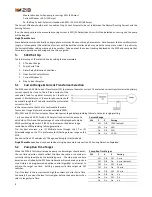
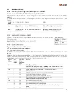
Current Range
SW
1
2
Setting
Off
Off
100% (default)
Off
On
50%
On
Off
25%
On
On
12.5%
Pump Run Time Target
SW
3
4
5
Setting
Off
Off
Off
3 min
Off
Off
On
5 min (default)
Off
On
Off
8 min
Off
On
On
15 min
On
Off
Off
30 min
On
Off
On
1 h
On
On
Off
2 h
On
On
On
4 h


