


2
1.
Safety
SAFETY WARNINGS:
Always isolate the power supply before performing any installation work.
Always isolate the power supply before attempting to trace a fault as the pump connected may start without
warning.
The installation shall be performed by an authorised electrician according to local safety regulations.
The SC10 must only be used on pumping equipment that is capable of running dry for short durations.
The SC10 is not to be used in Hazardous Areas or Locations (such as areas with Explosive or Flammable Gas or Dust
Environments).
There are no operator serviceable parts inside. Modification may negatively impact safety and may void warranty.
2.
Unpacking, Inspection and Recycling
The delivery comprises of:
1 x SC10 Pump Control Unit
1 x SC10 Installation and Operations Manual. (This document.)
1 x SC10 Quick Reference Guide
If any of these items are missing or damaged at the time of delivery, please contact 2iB Pty Ltd. Please retain the product packaging
and return the product for inspection if damaged.
A 4-20mA CT is required for snore control operation. This can be purchased separately from 2IB.
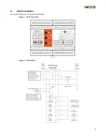
3.
Installation
3.1
Important Installation Requirements
To avoid damage: If the Power Supply is to be earthed then terminal no. 2 (-) may be earthed, but not terminal no. 1
(+).
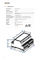
Check that the rated voltage of SC10 corresponds with the supply line voltage. The SC10 is mounted on a standard 35
mm DIN rail. Ensure that you use the SC10 within its Technical Specifications – see section 8 Specifications.
To ensure accuracy and reliability screened twisted-pair cable is to be used for connection of the Current Transducer for
measuring the pump motor current.
3.2
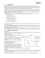
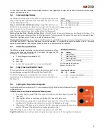
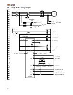
Remote Snoring Setup Controls for Operator Safety
The Stop Current Setpoint can be set and adjusted using pushbuttons on the front of the pump starter / control panel. This enables
the pump setup, commissioning and setpoint adjustment to be performed without the electrical hazards entailed in opening the
pump starter / control panel doors.
As shown in section 9 SC10 Connections the pushbuttons can be connected to digital inputs on the SC10. It is recommended to
connect / provide pushbuttons for:
Up (Setpoint Adjustment)
Down (Setpoint Adjustment)
Set (Set the Stop Current Setpoint)
Start (Pump Start – needed for commissioning)
If you wish to prevent unauthorised personnel making adjustments then you can install these pushbuttons behind a lockable door
or cover.
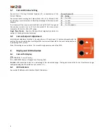
3.3
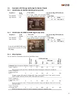
Front-Mounting of SC10 to View Operating Current and Access Pushbuttons
In addition to the standard mounting of the SC10 on a DIN Rail inside the cabinet, two alternative mounting options can be
considered:
A window can be built into the starter cabinet door and the SC10 can be mounted forward of the back-plate / gear-tray
(or on the rear of the door) so that the current display is visible from outside of the panel.
The SC10 can be mounted so that the front of the SC10 protrudes through the door (similar to circuit breakers) thus
providing access to the current display as well as the buttons. Note that the SC10 is neither dust, nor water resistant so
an outer door or cover will be required. (WARNING: Please take into account local and site electrical safety
requirements.)


