


2
Copyright © 2014 Linear LLC
Go!Bridge IP Communicator | Installation Instructions
NOTE:
If
the
900MHz
LED
illuminates
in
GREEN
(the
lower
LED),
verify
that
the
network
cable
is
not
connected
to
the
Go!Bridge
IP
Communicator.
If
the
cable
is
disconnected
and
it
is
still
illuminated
GREEN,
use
the
end
of
an
open
paperclip
to
press
and
release
the
recessed
Reset
button.
The
button
is
located
inside
the
small
hole
on
the
port
side
of
the
Go!Bridge
IP
Communicator,
directly
above
the
Ethernet
port.
This
restores
the
factory
settings.
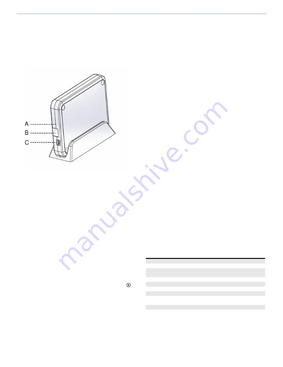
See
Figure
3
Go!Bridge
IP
Communicator
Rear
View—Ports
and
Recessed
Reset
Button.
Figure 3
Go!Bridge IP Communicator Rear View
—
Ports and
Recessed Reset Button
5
After
the
Go!Bridge
IP
Communicator
is
powered
ON,
continue
with
Programming
the
Go!Bridge
IP
Communicator
into
the
Control
Panel
.
Programming the Go!Bridge IP Communicator
into the Control Panel
Use
these
steps
to
place
the
control
panel
and
Go!Bridge
IP
Communicator
in
learning
mode.
This
gives
the
control
panel
the
ability
to
learn
the
network
settings
transmitted
by
the
Go!Bridge
IP
Communicator.
NOTE:
To
scroll
between
op ons
on
the
control
panel,
tap
the
←
and
→
arrows.
To
move
to
the
previous
or
next
prompt
tap
the
↑
and
↓
arrows.
1
Connect
an
Ethernet
cable
(not
included)
to
the
router
and
Go!Bridge
IP
Communicator.
Do
not
plug
the
cable
into
the
uplink
port.
IMPORTANT:
For
compliance
with
UL
1023:
Household
Burglar
‐
Alarm
System
Units
,
the
Go!Bridge
must
be
installed
in
the
same
room
as
the
Internet
modem
or
router.
2
Ensure
the
control
panel
is
powered
ON.
Then
tap
the
Home
button.
3
Tap
the
system
logo
in
the
lower
‐
right
corner
of
the
control
panel
Home
screen.
4
At
the
Enter
Your
Code
screen,
enter
the
four
(4)
‐
digit
master
installer
code
to
go
to
the
Installer
Toolbox
(1
of
2)
screen.
5
At
the
Installer
Toolbox
(1
of
2)
screen,
tap
System
Configuration
.
6
At
the
Q1:
Select
RF
Sensor
#
(01
to
48)
screen,
tap
Go
To
.
7
At
the
Enter
Question
Number
(2
Digits)
screen,
enter
92
.
8
At
Q92
Select
Network
Device
(0
to
1)
,
tap
→
to
scroll
to
(1)
Go!Bridge
IP
Communicator.
Then
tap
↓
.
9
At
Q:
Network
Device
ID
(Read
Only)
,
tap
Learn
.
This
gives
the
panel
the
ability
to
discover
the
read
‐
only
network
device
ID
transmitted
by
the
Go!Bridge
IP
Communicator.
At
the
Pair
with
Xcvr
Device
screen,
the
“initiating
learning
process”
message
appears.
10
On
the
Go!Bridge
IP
Communicator,
press
and
release
the
Learn
button
(this
is
the
small,
black
plastic
button
on
the
LED
side
of
the
Go!Bridge
IP
Communicator
below
the
900MHz
LED).
This
transmits
the
device
ID
to
the
Control
Panel.
When
the
“learn
operation
succeeded”
message
appears
and
the
panel
displays
the
Type
(Go!Bridge
IP
Communicator)
and
ID#
,
the
Go!Bridge
IP
Communicator
and
panel
are
linked.
The
900MHz
LED
on
the
Go!Bridge
IP
Communicator
also
flashes
GREEN.
11
At
the
Pair
with
Xcvr
Device
screen,
tap
OK
.
Then
tap
↓
to
continue
with
Configuring
the
Go!Bridge
IP
Communicator
Settings
below.
Configuring the Go!Bridge IP Communicator Settings
1
At
the
Q:
Select
Port
#
(1
to
8)
screen,
enter
the
port
number
for
the
third
‐
party
monitoring
services’
server.
Then
tap
↓
.
2
At
Q:
Used
(0
to
1)
,
tap
→
to
select
one
(1)
of
these
options:
•
(0)
Disabled
(Recommended).
This
is
the
default
setting.
Most
users
will
keep
this
port
disabled.
Then
tap
Next
and
skip
to
step
3.
OR
•
(1)
Enabled
.
Then
tap
↓
.
At
the
Q:
Enter
Port
Value
(0
‐
65535)
screen,
tap
↓
to
accept
the
default
port
value.
Next,
at
the
Q:
Enter
Port
Forward
IP
Address
screen,
tap
↓
to
accept
the
address
configured
by
the
provider.
You
can
configure
up
to
eight
(8)
ports.
If
you
are
finished
configuring
ports,
tap
Next
.
3
At
the
Summary
of
Network
Device
screen,
tap
↓
.
Verify
the
list
of
port
numbers
and
forward
IP
addresses
appears
as
programmed.
Then
tap
Skip
.
4
At
Q93
Enter
Broadband
Network
Failure
Time
(1
to
255)
,
enter
the
desired
number
of
minutes
that
must
pass
before
a
network
failure
triggers
the
Control
Panel
to
issue
a
trouble
alert.
The
default
value
is
30
minutes.
Then
tap
↓
.
NOTE:
A
trouble
alert
consists
of
an
audible
beep
and
the
Control
Panel’s
Home
screen
displays
a
trouble
message.
5
At
Q94
Select
Broadband
Network
Failure
Report
(0
or
1)
,
tap
→
to
select
whether
or
not
to
report
the
broadband
network
failure
to
the
monitoring
service:
•
(1)
Enabled
.
This
is
the
default
setting.
Network
failures
are
reported
to
monitoring
service.
OR
•
(0)
Disabled
.
Network
failures
are
not
reported.
6
Tap
End
.
7
At
the
Summary
of
System
Configuration
screen,
verify
the
settings.
Then
tap
Save
Changes
.
8
Tap
Exit
to
the
close
the
System
Configuration
screen.
LED Indicators
The
table
details
the
LED
indicators
on
the
Go!Bridge
IP
Communicator.
A
Recessed
Reset
Button
B
Ethernet
Port
C
Power
Supply
Port
Network
LED
Globe
Icon
Solid
GREEN
Indicates
the
presence
of
an
external
network
connection.
Flashing
GREEN Network
cable
is
plugged
in
and
IP
address
is
actively
being
assigned.
Solid
RED
Network
cable
unplugged.
900
MHz
LED
Icon
Labeled
“900MHz”
Solid
GREEN
Linked
and
communicating
with
the
Control
Panel.
Flashing
GREEN Linked
to
the
Control
Panel.
Communication
issues
exist.
Solid
RED
Not
linked
to
the
Control
Panel,
turns
solid
after
a
device
reset.
Flashing
RED
Not
linked
to
the
Control
Panel.


