-8-
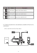
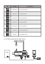
DIP
Bit State
Descriptions
OFF,OFF,ON
Set to the second DT-RLC.
ON,OFF,OFF
Set to the third DT-RLC.
ON,OFF,ON
Set to the fourth DT-RLC.
OFF,ON,OFF
Set to the fifth DT-RLC.
OFF,ON,ON
Set to the sixth DT-RLC.
ON,ON,OFF
Set to the seventh DT-RLC.
ON,ON,ON
Set to the eighth DT-RLC.
1
2
3
ON
1
2
3
ON
1
2
3
ON
1
2
3
ON
1
2
3
ON
1
2
3
ON
1
2
3
ON
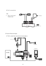
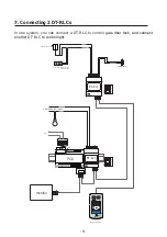
6.3 DT-RLC Connections for Light Control
110~250V AC Input
BUS(IM) BUS(DS)
PC6
GND
S1
S2
12V
NC
COM
NO
GND
AC~
monitor
-
+
L1 L2 PL S+ S-
(Device Address:0)
NO
POWER IN-USE
BUS
GND
COM NC
DT-RLC
2-WIRE SYSTEM
12V
S2
S1 GND
BUS
RISER
1
2
3
1
2
3
ON
DIP

