background image


Ident

ifi

cat

ion

: M

D

-AL

-GI

-00


R

ev

. 1.

of

 24

/06/

21 

- A

ppl

ic

at

ion:

 G

ID


Zucchetti Centro Sistemi S.p.A. - Green Innovation Division 
Via Lungarno, 248 - 52028 Terranuova Bracciolini - Arezzo, Italy  
tel. +39 055 91971 - fax. +39 055 9197515 
[email protected] - [email protected] - 

zcsazzurro.com


Pile Reg. IT12110P00002965 - 

Share Capital € 100,000.00 fully paid up 

AR Company Reg. no. 03225010481 - REA AR no. 94189 
ISO 9001 Certified Company - Certificate no. 9151 - CNS0 - IT-17778 


“Connext System User Manual” of 10/01/2023 Rev. 2.2


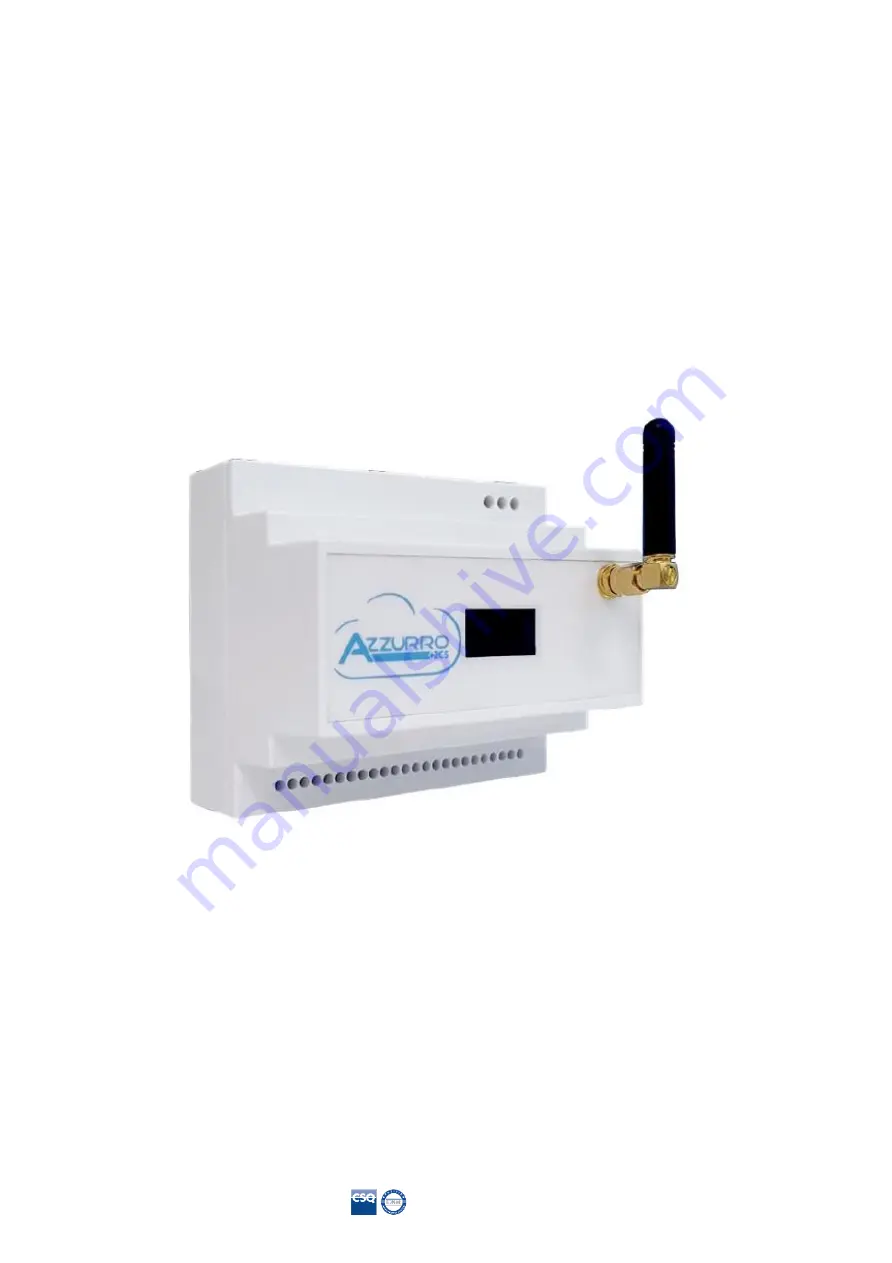
“CONNEXT” Control System


User Manual 


Summary of Contents for AZZURRO CONNEXT

Page 1: ...lini Arezzo Italy tel 39 055 91971 fax 39 055 9197515 innovation zcscompany com zcs pec it zcsazzurro com Pile Reg IT12110P00002965 Share Capital 100 000 00 fully paid up AR Company Reg no 03225010481...

Page 2: ...ferred to another user or plant Copyright statement The copyright of this manual belongs to Zucchetti Centro Sistemi S p A No part of this manual including the software etc may be copied reproduced or...

Page 3: ...verter 23 5 2 Configuration 2 System with Azzurro 3000SP inverter 26 5 3 Configuration 3 System with Azzurro three phase hybrid inverter 28 5 4 Configuration 4 System with Azzurro single phase photovo...

Page 4: ...agement 53 8 1 Setting dry contacts from app 53 9 Access for maintenance only 56 9 1 Access connection for maintenance only 56 10 Technical datasheet 57 11 Maintenance 58 11 1 Troubleshooting 58 11 2...

Page 5: ...sonnel or anyone who is qualified and certified to work on an electrical system responsible for installation and start up of the system The manual is also intended for end users who can find useful in...

Page 6: ...a hazardous situation which if not resolved or avoided could result in minor or moderate personal injury Caution Attention indicates a potentially hazardous situation which if not resolved or avoided...

Page 7: ...rised service centre for any repairs or maintenance Contact your distributor for information on the nearest authorised service centre DO NOT carry out repairs yourself as this may result in injury or...

Page 8: ...y by road must be carried out with vehicles suitable to protect the components especially the electronic components against violent knocks humidity vibrations etc Electrical connections Please follow...

Page 9: ...o the electrical grid Follow all the instructions and safety requirements relating to grid connection Danger If the system is not functioning properly Disconnect the input and output power supply Warn...

Page 10: ...Solo documento principale 10 67 Identification MD AL GI 00 Rev 1 2 07 06 21 Application GID Connext User Manual Rev 2 2 10 01 2023 Labels Figure 2 Labels on the System...

Page 11: ...ion The Connext control system is able to communicate with Azzurro electric vehicle charging stations and Azzurro photovoltaic inverters It can also measure energy consumption monitor systems and safe...

Page 12: ...system connection in a three phase system Overall dimensions H W D 105 mm x 85 mm with antenna installed x 89 mm 2 2 Product overview Connext can be installed on DIN bar 8 modules and powered by a 230...

Page 13: ...6 24 pin terminal block The 24 pin terminal block has the following pin out PIN Connection PIN Connection 1 Not used 13 Relay1 normally closed contact 2 Digital output 2 14 Relay1 common contact 3 Di...

Page 14: ...ximum acceptable cable cross section for the terminals is 1 5mm2 SD card slot The push push SD card slot allows the use of a microSD card with maximum capacity of 8 GB The card is inserted and removed...

Page 15: ...kaging materials and components may be damaged during transport Therefore please check the materials of the outer packaging before installation Check the surface of the box for external damage such as...

Page 16: ...ge contents Installation tools The following tools are required for installation and electrical connections therefore they must be prepared before installation No Tool Function 1 Screwdriver To screw...

Page 17: ...om and to the ground if the devices are installed at a height of more than 180 cm Devices installed at greater heights must be moved to the ground before they can be repaired or serviced 3 3 Materials...

Page 18: ...uct Installation must be carried out by a qualified professional with the skills and knowledge to build install and operate electrical components and who has been trained on how to identify and preven...

Page 19: ...cation GID Connext User Manual Rev 2 2 10 01 2023 Cable connection procedure 1 Remove a suitable length of the protective sleeve as shown in the figure A 80 100 mm B 6 8 mm Figure 8 Connecting AC powe...

Page 20: ...EV charging stations can be connected in cascade Connect the Connext system to the first EV charging station according to the instructions given here 1 Connect the 8 pin cable to the ports indicated...

Page 21: ...uitable length of the protective sleeve as shown in the figure A 80 100 mm B 6 8 mm Figure 11 Preparing the CAN bus cables 4 Connect the cables according to the table below Pin RJ45 Cable colour Conne...

Page 22: ...ing the RJ45 connectors of the CAN ports as in out Only the first wallbox is connected to the Connext system Consult the manual of the charging station to check the firmware version installed If it is...

Page 23: ...e To connect to hybrid storage or photovoltaic inverters follow the instructions in the sections below NOTE IF THE SYSTEM HAS ONE OF THESE INVERTERS 1PH HYD3000 HYD6000 ZSS 3PH HYD5000 HYD20000 ZSS 30...

Page 24: ...e sleeve as shown in the figure A 80 100 mm B 6 8 mm 2 Connect the 2 pole cable to the pins of the HP hybrid inverter marked RS485 Follow the polarity shown in the figure and the pin out in the table...

Page 25: ...cation GID Connext User Manual Rev 2 2 10 01 2023 Figure 16 RS485 connections to single phase hybrid inverter Figure 17 Connections on single phase hybrid inverter RS485 Pin 24 pin terminal block RS48...

Page 26: ...0SP inverter THE SENSOR OR SENSORS FOR MEASURING THE EXCHANGE MUST BE CONNECTED TO THE INVERTER ACCORDING TO THE MANUAL Figure 18 Configuration 2 with 3000SP retrofit inverter Follow the instructions...

Page 27: ...the 2 pole cable to the port of the 3000SP inverter marked RS485 Follow the polarity shown in the figure and the pin out in the table Figure 20 Connections on 3000SP inverter RS485 Pin 24 pin terminal...

Page 28: ...se hybrid inverter Figure 22 Configuration 3 with three phase hybrid inverter THE SENSORS OR METER FOR MEASURING THE EXCHANGE MUST BE CONNECTED TO THE INVERTER ACCORDING TO THE MANUAL Follow the instr...

Page 29: ...Preparing RS485 cables 2 Connect the 2 pole cable to the port of the hybrid inverter marked COM Follow the polarity shown in the figure and the pin out in the table Figure 24 Connecting on COM Port fo...

Page 30: ...nnections with three phase hybrid inverter 5 4 Configuration 4 System with Azzurro single phase photovoltaic inverter A SENSOR MUST BE MOUNTED ON THE CONNEXT SYSTEM FOR MEASURING THE EXCHANGE Figure 2...

Page 31: ...nect the 2 pole cable to the port of the photovoltaic inverter marked RS485 Follow the polarity shown in the figure and the pin out in the table For V1 and V2 models refer to the connection on the lef...

Page 32: ...g inverter Figure 30 Connection of exchange sensor on Connext The CT must be positioned according to the diagram shown in Figure 26 Then check the direction of the current measured by the CT Procedure...

Page 33: ...h Azzurro three phase photovoltaic inverter Figure 31 Configuration 5 with three phase string inverter Follow the instructions to connect the RS485 port to Azzurro three phase photovoltaic inverters 1...

Page 34: ...ovoltaic inverter The exchange must be measured via a three phase meter configured as follows Figure 33 RS485 connection on meter side Pin Meter 24 pin terminal block 24 9 25 10 Table 12 RS485 connect...

Page 35: ...S 3PH HYD5000 HYD20000 ZSS 3000SP REFER TO THE RESPECTIVE MANUALS FOR CONNECTING THE SENSORS ZSM ACC TA AND OR THE METER DTSU666 Figure 35 Configuration 6 with NON Azzurro photovoltaic inverter 6 1 Co...

Page 36: ...36 NON Azzurro production sensor connection on Connext Sensor cable 24 pin terminal block Black cable 23 Red cable 24 Table 14 Exchange sensor connections Figure 37 Connection of exchange sensor on Co...

Page 37: ...ot the case change the direction of the CT 6 2 Configuration 7 System with three phase photovoltaic production Figure 38 Configuration 7 with NON Azzurro string inverter If at least one three phase ph...

Page 38: ...2 2 10 01 2023 Table 15 Photovoltaic sensor connections Figure 39 Connection of NON Azzurro production sensor on Connext Figure 40 RS485 connection on meter side Pin Meter 24 pin terminal block 24 9 2...

Page 39: ...gure 41 RS485 connections with exchange meter Follow the meter s manual to configure it correctly setting the communication address to 32 The direction of the arrow on the current sensor represents th...

Page 40: ...re is no Azzurro string or hybrid inverter the Connext can still be used to manage the wallbox It is only necessary to measure the exchange with a sensor The sensor must be positioned directly at the...

Page 41: ...07 06 21 Application GID Connext User Manual Rev 2 2 10 01 2023 Figure 43 Connection of exchange sensor on Connext 6 4 Configuration 9 Three phase system without photovoltaic production Figure 44 Con...

Page 42: ...DTSU must be installed The Meter must be placed directly on the output of the exchange meter and connected to the Connext system via the RS485 port following the pin out shown Figure 45 RS485 connecti...

Page 43: ...ft or LAN right 7 1 Creating an account on the Azzurro Systems app For the initial configuration simply follow the instructions given in the Azzurro Systems App which can be downloaded for Android and...

Page 44: ...Yes No Change charging strategy EVC Yes Yes No System monitoring Yes Yes Yes Table 19 Account levels Figure 49 Access to Azzurro Systems app Any systems already registered on the account used will be...

Page 45: ...1 2023 Figure 50 Add system with Connext Figure 51 Configuration of system with Connext 1 If Connext has already been registered by an account it will no longer be possible to become its owner The pow...

Page 46: ...ure 52 Configuration of system with Connext 2 The system configuration must be indicated whether single phase or three phase IMPORTANT do not indicate whether it is a single phase or three phase inver...

Page 47: ...guration is complete the list of connected devices and the settings of the system can be checked Figure 54 Adding devices To add devices click the icon click Add inverter and enter the serial number o...

Page 48: ...ss 7 3 Adding measuring systems There are different options an inverter and sensors cannot be inserted on the same system If there is no inverter select Add sensors To add measuring devices in Configu...

Page 49: ...next User Manual Rev 2 2 10 01 2023 Figure 56 Adding measuring sensors 7 4 Adding and managing wallboxes NB the wallbox is recognised automatically Make sure it is powered and set on Plug Play If the...

Page 50: ...Rev 1 2 07 06 21 Application GID Connext User Manual Rev 2 2 10 01 2023 Figure 58 Wallbox operating status When the connector of the car is plugged in and if the car itself allows it the charging can...

Page 51: ...Pure The wallbox uses all the photovoltaic output to charge the car subject to the maximum current set from the display and the maximum current accepted by the car Obviously the presence of other loa...

Page 52: ...Solo documento principale 52 67 Identification MD AL GI 00 Rev 1 2 07 06 21 Application GID Connext User Manual Rev 2 2 10 01 2023 Figure 60 Charging strategies...

Page 53: ...low for physical connections Output on app 24 pin terminal block Output 1 3 4 Output 2 2 4 Output 3 16 17 18 Output 4 13 14 15 Table20 Output settings on app 8 1 Setting dry contacts from app ONLY THE...

Page 54: ...Solo documento principale 54 67 Identification MD AL GI 00 Rev 1 2 07 06 21 Application GID Connext User Manual Rev 2 2 10 01 2023 Figure 62 Setting dry contacts 2 Figure 63 Setting dry contacts 3...

Page 55: ...n heat pump off When this value is reached the contact closes and the logic comes into operation It is kept active until the minimum threshold W or is verified The threshold is checked by default ever...

Page 56: ...r cables of the Connext system in the 3 pin terminal block are NOT connected powered L and N power cables disconnected from the system MUST not be powered so as to prevent the risk of electric shock C...

Page 57: ...Solo documento principale 57 67 Identification MD AL GI 00 Rev 1 2 07 06 21 Application GID Connext User Manual Rev 2 2 10 01 2023 10 Technical datasheet...

Page 58: ...ication GID Connext User Manual Rev 2 2 10 01 2023 11 Maintenance 11 1 Troubleshooting Follow the access procedure for maintenance and contact the supplier Visit the website www zcsazzurro com 11 2 Ma...

Page 59: ...the AC mains power supply Remove any communication connections Remove from the DIN bar support 2 Packaging If possible pack the system in its original packaging 3 Storage Store the system in a dry pl...

Page 60: ...ing in the proper disposal of this product you contribute to the reuse recycling and recovery of the product and to the protection of our environment 13 Warranty terms and conditions To view the Warra...

Page 61: ...using the front keypad Back Next Cancel Back Confirm Enter Figure 65 Control keypad 1 Press the Confirm Enter key for at least 10 seconds 2 The page shown in the figure below appears use the Next Back...

Page 62: ...t the desired working mode i e Plug Play just plug in the car to automatically start the charging cycle Wait 120 sec for the setting to become active then switch the device off and on again Using RFID...

Page 63: ...ure 70 RFID card control screen 3 To add charge enabling cards select 1 Add Card and place the RFID card in front of the symbol below Figure 71 Add card screen Up to 8 RFID cards can be registered The...

Page 64: ...d to PIN 1 red wire and PIN 3 black wire S phase measurement with the terminals connected to PIN 4 red wire and PIN 6 black wire T phase measurement with the terminals connected to PIN 7 red wire and...

Page 65: ...e settings menu as shown below 1 Press SET and the word CODE will appear 2 Press SET again and 600 will appear 3 Enter the number 701 a From the first screen where the number 600 appears press the key...

Page 66: ...the menu ii Write 40 1 From the first screen where the number 1 appears press the key several times until the number 10 is written 2 Press SET once to move the cursor left highlighting 10 3 Press the...

Page 67: ...Solo documento principale 67 67 Identification MD AL GI 00 Rev 1 2 07 06 21 Application GID Connext User Manual Rev 2 2 10 01 2023 iii Press ESC to confirm...

Reviews: