background image

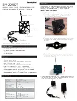
ZBL-R630A Rebar Detector 


Dahecinst 


[email protected] 

[email protected] 


+52 5586114372 
+52 7791340470 


Content


1.


Introduction ---------------------------------------------------------------------------------------------------------------------- 3 


1.1


Principle 


1.2


Functions 


1.3


Features 


1.4


Technology Data Sheet 


1.


5 Packaging List 


1.6


Safety Instructions 


1.7


Maintenance 


1.8


Responsibilities 


2.


Starting Measurement ---------------------------------------------------------------------------------------------------------- 6 


2.1


Port of ZBL-630A 


2.2


Keyboard 


2.3


Charging port 


2.4


USB port 


2.5


Sensor port 


2.6


Sensor 


2.7


Power supply charger 


2.8


Signal wire 


2.9


U-disk 


2.10


Starting-up interface and Main menu 


2.11


Keyboard operation 


2.12


USB transmission 


2.13


System setting 


2.14


Introductions of rebar test 


3.


Rebar Test ---------------------------------------------------------------------------------------------------------------------- 10 

Summary of Contents for ZBL-630A

Page 1: ...ng List 4 1 6 Safety Instructions 4 1 7 Maintenance 5 1 8 Responsibilities 5 2 Starting Measurement 6 2 1 Port of ZBL 630A 6 2 2 Keyboard 6 2 3 Charging port 6 2 4 USB port 6 2 5 Sensor port 7 2 6 Sensor 7 2 7 Power supply charger 7 2 8 Signal wire 7 2 9 U disk 7 2 10 Starting up interface and Main menu 7 2 11 Keyboard operation 8 2 12 USB transmission 8 2 13 System setting 8 2 14 Introductions of...

Page 2: ...id scan 17 3 3 Profile scan 24 3 4 Data display 26 3 5Data check of ZBL R630A 26 3 6Rebar data deletion 27 3 7On site test 28 4 Guide of quick operation 33 4 1On site preparation 33 4 2To connect sensor to host 33 4 3Starting test 33 4 4Data transmission 33 4 5Data analysis and process 33 4 6Data deletion 33 4 7Attention for field detection 34 ...

Page 3: ...ess of concrete cover automatically Test data storage check and transmission Analyze professionally with Test Data Processing Software 1 3 Features Unique all wheel dustproof and waterproof multi parameter rebar probe ensures accuracy and reliability of data taking Rebar detection is automatically alerted by the probe via flashing red light Store data in U disk Powerful professional analysis proce...

Page 4: ...ent Environmental temperature 0 40 Relative humidity 90 RH Long time sunlight perpendicular incidence is avoided Anti corrosion when used under damp dusty and full of corrosive gas conditions protective measures are necessary Requirements for storage environment Environmental temperature 20 60 Relative humidity 90 RH Out of use please place instrument into package store in a ventilated cool and dr...

Page 5: ...ent Good ventilation is necessary for heat dissipation Attention Avoid charge with other power adapters or it will cause damage to instrument Rechargeable battery When battery is near the end of service life after frequent charges and discharges if the battery works abnormally cannot charge with electricity cannot charge full or short time is used after full charge it is probable that rechargeable...

Page 6: ... decrease etc SAVE To save the test data time number and parameter etc ENTER Parameter choice and determination or change of testing direction Power key opening and closing of instrument 2 3 Charging port To charge instrument with battery charger attached with the instrument 6 8 hours is suggested in order to have a full charge 2 4 USB port Port for connection with U disk is on the left side of in...

Page 7: ...ensor in real time accurately While going forward sensor scans rebar and backward scrubs it Figure 2 2 2 7 Power supply charger Entry plug connects with 100 240V AC power supply and exit plug into charging plug of host for charging of inside lithium battery 2 8 Signal wire Instrument signal wire consists of rebar sensor signal wire Ports of signal wire are on the left of baffle 2 9 U disk It is us...

Page 8: ...u interface pressing to choose whether open or close backlight ENTER selects specific option SAVE stores data and parameter BACK goes back to previous interface MENU goes back to main menu is power switch 2 12 USB transmission Plugging the U disk attached with instrument into USB port of the left side paddle and then selecting Data Output then press ENTER it will show the figure 3 2 Attention plea...

Page 9: ...rease or decrease by one After modification pressing SAVE to store the set time and go back to main menu If there is no need to change current time please press BACK or MENU to go back to main menu 2 14 Introductions of rebar test Rebar test is divided into General scan Profile scan and Grid scan Press and keys in main menu interface as shown in figure 3 1B to choose Rebar Test and press ENTER to ...

Page 10: ...ce quantity of electricity will be tested When it is too low tip of lack of electricity please charge will be presented on the middle of interface and vocal warning requires immediate charging at that time users should not continue parameter setting or tests or data is easy to lost or make error It is better to exit from testing interface and go back to main menu then shutdown finally change batte...

Page 11: ...nd 50mm and the default value is the setting value of previous stored object Pressing in figure 3 7 to shift cursor to Dia then press ENTER to set the diameter pressing or key can increase or decrease by 1 rebar standard Long time pressing of or key can increase or decrease the value consecutively After it is done pressing SAVE or ENTER for storage cursor will disappear and go back to parameter se...

Page 12: ...d improve test accurately It is divided into Manual and None After starting the default one is None no correction While Manual means modifying based on center distance of adjacent rebars set manually and displays the measured results after correction Pressing in figure 3 7 to shift cursor to Corr then press ENTER to set the correction mode pressing and can achieve shift between Manual and None If ...

Page 13: ... the minimum value of current thickness is the thickness of cover If users used data correction it only shows measurement value not corrected one Cover display of measurement value unit mm of thickness of concrete cover automatically If users used data correction it shows the corrected value Dia display of measurement diameter of tested rebar unit mm pressing key for measurement of diameter and th...

Page 14: ...large situations represented by and respectively In the test interface shown in figure3 7 pressing for shift the range and shown or in status bar Every time entering into this interface the default one is the first 2 Method of storage to select the method of storage of tested result It is divided into 2 types automatic and manual marked with A and M respectively Manual storage only when pressing S...

Page 15: ...n 1 In the detection process a reset operation should be done about every 10 minutes 2 While doubt on the measurement data measure again after resetting 3 1 3 2 Identify the direction of rebar and thickness of cover Just as shown in figure3 10 placing sensor on the surface of tested concrete and paralleling with tested rebar then moving sensor along a direction in a uniform speed when sensor going...

Page 16: ...irection of sensor is the direction of tested rebar figure3 11 D 3 1 3 3 Measurement of rebar diameter 1 Resetting sensor in accordance with the method 2 2 Identifying rebar s location and direction precisely 3 Placing the sensor above the tested rebar and paralleled with it Pressing key after about 2 seconds the tested result of diameter will be directly shown in the position of Dia The instrumen...

Page 17: ...ame with 3 6 1 pressing and keys to shift to options for setting and pressing ENTER for selection pressing and keys for modification and shifting and finally pressing SAVE to store the set value and exit from it Dia X the diameter of awaiting measuring rebar in X direction and the setting range is 6 50mm the default value is the set one of previous stored object Dia Y the diameter of awaiting meas...

Page 18: ...rollbar displays the current thickness of cover a little difference compared with data of general scan Blank no rebar in sensing range of sensor Increase sensor is moving towards rebar Decrease sensor is moving away from rebar Coordinate on the top left Figure 3 15 Superscripts of grid scan The measurable length of X and Y is 1 meter in one screen if more than 1 meter then flip the page and the pa...

Page 19: ...ckness will show in blank After nearly 4 seconds screen of test interface will show the present thickness is 0 then resetting is over waiting for measurement 3 1 5 1 Pre scanning When entering into interface in figure 3 14 after resetting instrument can pre scan The purpose of pre scanning is to identify the direction of measuring line and the starting point through initial scanning of distributio...

Page 20: ...curs showing the present displacement of sensor the displacement is relative one compared with coordinate points in this page then scanning can be started in X direction shown in figure3 17 Moving sensor in a uniform speed when the senor is closer with rebar scrollbar will lengthen gradually the current thickness value in the upper right will decrease accordingly When sensor goes over rebar peep a...

Page 21: ... in accordance with GB50204 2002 symbol will occur or it will be blank If there is no second scanning pressing BACK key to go back to parameter setting interface or MENU to go back to main menu Retest in the test interface if there is any data error making sensor moves in reverse direction along the original path and goes back to the front of rebar with error at that time tested data and displayed...

Page 22: ...h rebar 2 In the second scan it only displays coordinate of rebar but not draws while scanning over rebar 3 Fifth step when scan distance go over the distance displayed by one screen the instrument turn to the second screen as shown in figure3 23 zero point of coordinate in the upper left will increase one correspondingly Users can continue scanning in this interface The maximum distance can not b...

Page 23: ...No m 1 rebar and No m rebar No m rebar is the last rebar in first scanning of this direction as shown in figure3 25 Figure 3 25 Second scanning in Y direction Second scanning in Y direction can be seen in figure3 26 figure a is the starting state of scanning in Y direction Figure b is screen scrolling scanning state in Y direction Attention The starting point of every measurement should be in same...

Page 24: ...ines in both first and second scanning in the same direction prepared for Windows software analysis As to the usage of Windows software users can see rebar data processing software manual Attention In cross rebar second scanning the measuring line should keep away from the measuring line of first scan in the same direction In restrict sense the actual distribution diagram of cross rebar scanning w...

Page 25: ... 3 you can also press SAVE key to enter into test a square cursor will occur in the top left corner while testing moving sensor in an uniformed speed when sensor is getting closer to rebar scroll bars lengthen gradually the current thickness value decreases When sensor goes over rebar peep alarming the tested rebar will be displayed in coordinate shown in pachytene in figure3 30 Thickness value of...

Page 26: ...rface it can return to main menu interface Pressing or on interface in figure3 31 you can move cursor to the desired check object Right side will display corresponding statistics of this object Pressing ENTER to enter into data check state displaying stored tested data of selected object 3 5 Data check of ZBL R630A 3 5 1 Data check of General scan If the object is tested by general scan the data d...

Page 27: ... interface in figure3 31 3 5 2 Data check of Grid data Pressing ENTER key on the interface in figure 3 33 a and entering into grid data display interface in figure3 33 b pressing for page turning check In any interface during data display pressing BACK key can go back to interface shown in figure3 33 a and pressing MENU to go back to main menu 3 5 3 Data check of profile Pressing ENTER key on the ...

Page 28: ... menu and press ENTER to enter into parameter setting interface 2 To set default diameter 3 To set minimum value of thickness to 0 4 To set object No optional 5 To hold sensor in the air without moving and keep away from ferromagnet 6 To press BACK to enter into test interface 7 After nearly 3 seconds the current thickness value will be 0 then resetting is completed entering into test state Attent...

Page 29: ...adually changes to smaller or the current thickness value becomes bigger Location of minimum thickness is the exact location of rebar 4 Scroll bar lengthens gradually then shorten When sensor approaches rebar the scroll bar will lengthen gradually or the scroll bar will shorten gradually The location of longest scroll bar is the exact position of rebar 3 7 3 To orientate rebar You can take followi...

Page 30: ...rise it can be determined that there is rebar and the thickness of cover is the minimum value during the above process For example when the current thickness value changes as follows there is rebar 63 62 61 62 63 and the thickness of cover is 61 3 To store the measured thickness of cover The thickness value automatically tested by instrument can be stored in group according to object No It can sto...

Page 31: ...of sensor and ensure the parallel between sensor and tested rebar 3 To try to select the larger position of cross bars for measurement 4 After completion of first scanning it is recommended for an inspection in reverse order to improve its reliability Attention when pure rebar space is less than 1 5 times rebar diameter and thickness of cover is greater than 2 times the space the last rebar can no...

Page 32: ...22 14 72 Ф25 14 74 Ф28 16 76 Ф32 16 77 Ф36 16 78 Ф40 20 80 Ф50 22 84 Firstly to locate rebar accurately and to identify precise direction of rebar placing sensor above the tested rebar and pressing key the word Dia will be displayed on the screen After a few minutes diameter measurement will be shown directly on the screen and the tested thickness value of cover shown after Cover is before this va...

Page 33: ...s the boot interface about 2 seconds it will enter into main menu interface automatically Select Rebar Test and press Enter to enter into test interface Please see chapter3 4 for specific operation 4 4 Data transmission After finishing the test transmit the testing data into U disk then into computer for analysis by software Please see chapter 3 2 for specific operation 4 5 Data analysis and proce...

Page 34: ... too rough and unable to remove placing a thin plate on scanning surface and minus thickness of the thin plate in test result 2 During scanning process try best to keep sensor one way uniform moving 3 Scanning direction should be vertical with rebar direction as shown in 4 9 or it may lead to misjudgement as shown in figure4 8 4 For grid rebar generally locate upper rebar firstly and the measure t...

Reviews: