background image

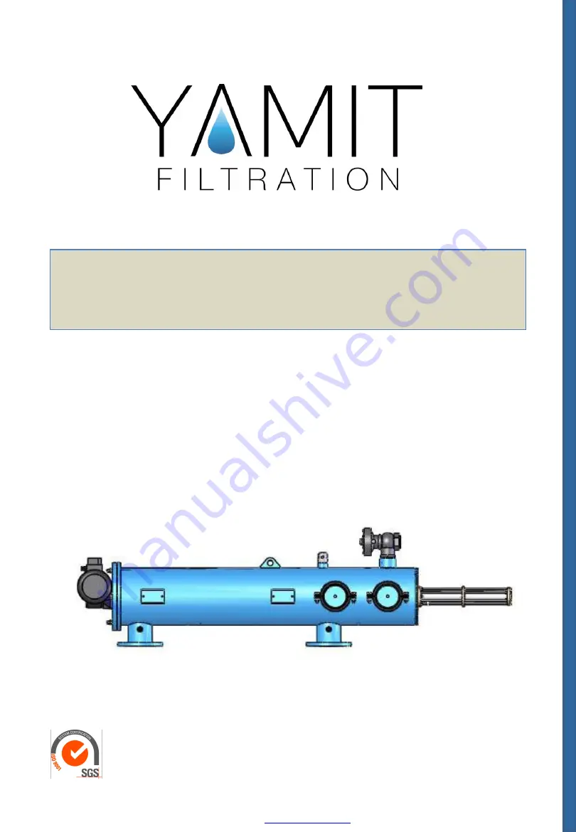
AF-9800 Series Electric Hydraulic  

Self-Cleaning Screen Filter 


SERVICE & MAINTENANCE MANUAL  

ENGLISH 

YAMIT Filtration & Water Treatment


Ltd

PO BOX 232 Moshav Tnuvot , 4283000 Israel 

Tel: +972-4-6220006  / e-mail: 

[email protected]

  /  www.yamit-f.com


18

-Oct

-20


Summary of Contents for AF-9800 Series

Page 1: ...ric Hydraulic Self Cleaning Screen Filter SERVICE MAINTENANCE MANUAL ENGLISH YAMIT Filtration Water Treatment Ltd PO BOX 232 Moshav Tnuvot 4283000 Israel Tel 972 4 6220006 e mail yamit yamit f com www yamit f com 18 Oct 20 ...

Page 2: ...n Assembly Removal Installation 13 6 5 Coarse Screen Removal Installation 14 6 6 Fine Screen Assembly Removal Installation 15 6 7 Dirt Collector Removal Installation 17 6 8 Periodical Checking 19 7 IPB 21 8 Appendix 28 8 1 ELI 02 Controller Electrical Wiring 28 8 2 Control Loops Drawing Baccara AC 34 8 3 Control Loops Drawing Galsol AC 35 9 International Warranty 36 ALL RIGHTS RESERVED THIS MANUAL...

Page 3: ...ify that the AC power cord is connected to the control panel through 3 x 6A fuse protector 4 Verify that the filter housing is grounded to the appropriate location 5 Confirm AC power disconnection prior to service 6 Confirm filter draining prior to service 7 Take precautions while lifting transporting or installing the filter 8 Installation and operation of the filter should be performed so as to ...

Page 4: ...3 Description Operation Filter Assembly General Description The AF 9800 Hydro electric self cleaning screen filter enables high quality filtering at filtering degrees of 10 3000 micron from different types of fluid sources such as sewage reservoirs rivers lakes and wells The AF 9800 SERIES filter contains the following parts Figure 1 filter assembly AF9800 ...

Page 5: ...draulic chamber 6 and the dirt collector 7 is significantly lowered resulting in a suction process via the suction nozzles 8 to the dirt collector 7 and from there to the hydraulic chamber 6 through the flushing valve 4 outside The electric motor 9 simultaneously rotates the dirt collector 7 around its axis The pressure is released from the piston 5 and the high pressure inside the filter causes l...

Page 6: ...lume LxWxH m ft AF9810X 250 10 16 720 28 35 1100 43 31 2787 109 72 3233 127 28 423 932 1 0x0 83x3 4 3 28x2 72x11 0 AF9812R 300 12 16 655 25 79 1100 43 31 2787 109 72 3233 127 28 428 944 1 0x0 83x3 4 3 28x2 72x11 0 AF9814R 350 14 18 770 30 31 1270 50 00 2787 109 72 3233 127 28 500 1102 1 0x0 83x3 4 3 28x2 72x11 0 AF9816R 400 16 18 770 30 31 1270 50 00 2787 109 72 3233 127 28 518 1142 1 0x0 83x3 4 3...

Page 7: ...nt Outlet ØD mm in Max Flow Rate m3 h gpm Screen area cm2 in2 Flushing Flow rate m3 h gpm Flushing Volume m gal AF9810X 250 10 400 1760 8410 1304 30 132 0 0833 22 0 AF9812R 300 12 600 2640 11710 1815 30 132 0 0833 22 0 AF9814R 350 14 900 3960 12990 2013 30 132 0 0833 22 0 AF9816R 400 16 1100 4850 12990 2013 30 132 0 0833 22 0 AF9816X 400 16 1500 6600 17020 2638 30 132 0 0833 22 0 Head loss AF9800 ...

Page 8: ...draulic flushing valve outlet opening at least 63 mm or 2 diameter and no longer then 5m Confirm that water runs freely out of the drainpipe 4 Position the control panel in such a way as to be protected against humidity and solar radiation 5 Connect the control panel to the power source 6 Check that all connections are properly secured 7 Check that all bolts and nuts on filter periphery are proper...

Page 9: ...onnect it immediately as flushing start 4 Verify that the hydraulic flushing valve closes after 10 seconds 5 Verify that the hydraulic piston fully extends during back flush 6 When the filter is clean verify that the differential pressure between inlet and outlet does not exceed 0 1 bar 7 Check that the differential pressure is set to 7 psi or 0 5 bar in the controller see appendix no 1 8 Perform ...

Page 10: ...splint out of the old motor axis groove 10 Carefully slide the new motor assembly into the filter assembly 11 Install the splint into the new motor axis groove 12 Install the four nuts and washers attaching the motor assembly to the filter assembly and the screw to the rear part of the motor 13 Connect the electric motor to the electrical power source according to the marking previously made in st...

Page 11: ...enoid 10 Connect the 2 electrical wiring to the control card terminals See Figure 5 11 Connect the solenoid control tubes 12 Connect the 4 X 1 5V batteries according to the correct polarity and close the electronic control unit cover 13 Perform a flushing cycle by disconnecting the low pressure tube from the differential pressure indicator closing of the electrical circuit re connect it immediatel...

Page 12: ...essure indicator into the control assembly 9 Install the two screws and nuts at the bottom of the electronic control unit assembly 10 Connect the two control tubes to the differential pressure indicator note that the high pressure and the low pressure connected to the right fittings 11 Connect the electrical wiring to terminals D and P on the electric terminal connection box 12 Set the main switch...

Page 13: ...lide the new piston assembly into the filter housing 10 Install the six nuts and washers connecting the piston assembly to the filter housing 11 Connect the control tube to the piston assembly aft section 12 Set the main switch at the control panel to 1 position 13 Open the inlet and the outlet line valves 14 Check for leaks 15 Perform a flushing cycle by disconnecting the low pressure tube from t...

Page 14: ... 9 Verify that the straight side of the body seal fits into the groove located in the cover 10 Put the cover into it s place on the filter Take care that the motor s dirt collector axis housing is slide on the dirt collector axis 11 Install the nuts and washers attaching the cover to the filter housing 12 Set the main switch at the control panel to 1 position 13 Open the inlet and outlet line valv...

Page 15: ...13 Lubricate upper and lower seals with silicon grease 14 Slide the dirt collector into the new fine screen 15 Install the screw on the top of the dirt collector axis 16 Slide the new fine screen assembly with the dirt collector into the filter housing assembly 17 Slide the coarse screen into the fine screen assembly 18 Verify that the straight side of the body seal fits into the groove located in...

Page 16: ...16 Figure 9 Fine Screen Assembly Removal Installation AF9800 ...

Page 17: ...irt collector into the new fine screen 13 Install the screw on the top of the dirt collector axis 14 Slide the fine screen assembly with the new dirt collector into the filter housing assembly 15 Slide the coarse screen into the fine screen assembly 16 Verify that the straight side of the body seal fits into the groove located in the cover 17 Put the cover into it s place on the filter Take care t...

Page 18: ...18 Figure 10 Dirt Collector Removal Installation AF9800 ...

Page 19: ...ector Removal Installation and check the dirt collector suction nozzles height see table If defective screw out the nozzle and replace with a new one 5 Check condition of the bearings replace if damaged or deformed 6 Remove the Piston according to piston removal installation check its condition clean it from sediments and replace seals if required 7 Check existence of grease on the motor axis 8 Ch...

Page 20: ...20 Figure 10 Periodical Checks AF9800 ...

Page 21: ...21 7 IPB AF9800 ...

Page 22: ...9814R AF9816R 5 AF9810X 4121203001 Washer M20 SS304 AF9812R AF9814R AF9816R AF9816X AF9818X 6 1 AF9810X 4112180401 Nut 3 4 NC AF9812R AF9814R AF9816R AF9816X AF9818X 6 2 AF9810X 4112180401 01 Nut 3 4 NC AF9812R AF9814R AF9816R 7 AF9810X E7006600301 01 Coarse screen PVC280 AF9810X 12R AF9812R AF9814R E7007600301 01 Coarse screen PVC315 AF9814R 16R AF9816R AF9816X E7008600301 01 Coarse screen PVC400...

Page 23: ...creen wheel 400 STEEL AF9818X 8 2 3 AF9800 5172301700 Screen bearing for shaft AF9 800 500B 700 9800N 8 3 AF9810X W5006600300 01 Fine screen middle section PVC280 AF9812R AF9814R W5007600300 01 Fine screen middle section PVC315 AF9816R AF9816X W5008600300 01 Fine screen middle section PVC400 AF9818X 8 4 AF9810X E5006600200 01 01 Fine screen lower section PVC280 ASSM AF9812R AF9814R E5007600200 01 ...

Page 24: ...0 01 Sealing rope housing BRASS AF5 75 98 18 1 AF9800 4082013100 U Ring 12 7 20 63 5 5 18 2 AF9800 4081030100 O Ring 30 3 18 3 AF9800 5182391300 Sealing rope housing AF5 75 98 18 4 AF9800 5319000900 Sealing rope 18 5 AF9800 5181391300 Tightening nut for sealing rope Brass AF5 75 98 19 AF9800 E5133301901 01 Comp Gear drive shaft SS304 AF9800 19 1 AF9800 5133301901 Gear drive shaft 18 9mm SS304 AF98...

Page 25: ... Flushing solenoid Which activates the flush filter hydraulic mechanism TP DP sw On Off Delay time Note that The internal on delay timer is provided to assure that accidental DP switch vibrating will not activate the flushing mechanism TD Flush Interval time Factory set to 9999 min can be adjust by the user TF Flush time Factory set to 5 sec can be adjust by the user TC Differential pressure check...

Page 26: ...gainst accidental short circuit on the PLC 8 FOUT 1 6ampT Fuse which protect against accidental short circuit on the solenoid outlets 24VDC C TERMINAL CONNECTIONS TB 1 4 L1 L2 L3 Gnd 115 230 380 420 440 480V 50 60 hz supply voltage inlets TB 5 8 U V W 230 380 420 440 480V GND 3 phase 50 60 hz motor supply voltage outlets TB 9 10 SV Flushing Solenoid outlet 24VDC 10W TB 11 12 DP Differential Pressu...

Page 27: ...wire TB7 TB8 Motor W phase wire TB8 TB9 SV flushing solenoid common 1 TB9 TB10 SV flushing solenoid live 2 TB10 TB11 DP switches common 3 TB11 TB12 DP switch live 4 TB12 2 Motor synchronization Motor synchronization must be carried out as follows Switch the MAIN switch to START position and Verify that ON L1 indicator lit Press push button FLUSH momentarily and Verify that FLUSH indicator lights a...

Page 28: ...hort circuit for min of 0 1 sec at REMOTE inlets 2 DP FLUSH cycle A DP flush is caused by a differential pressure across the filter Signal at DP inlet for DP ON TIME Factory set to 5 sec can be adjust by the user will activates the DP FLUSH mechanism while a DP signal absence for more than DP OFF TIME is consider as no DP signal Once a DP signal is registered the flushing mechanism will execute a ...

Page 29: ... state use the keys to change the field value When done press the OK key to enter the new value the field is blinking and darkened again 5 Move to other fields or exit to the main screen by pressing the ESC key until the main Screen appears PARAMETERS CHANGE UPDATE PROCEDURE When a desire parameter screen displayed it s value is darkened with black dotes In case of parameter with two fields like D...

Page 30: ...AGES DP FLUSH FAULT DP CHECK IN PROGRESS SET FLUSH INTERVALS RANGE 0 9999 hrs 0 9999 min SET FLUSH TIME RANGE 1 99 seconds SET DP CHECK TIME RANGE 1 999 seconds SET No OF CONSECUTIVE DP FLUSH CYCLES TO FLUSH FAULT RANGE 1 32000 DP flush Cycles SET DP ON OFF SENSE TIME RANGE 1 99 seconds SET SLAVE FLUSH ON DELAY RANGE 1 99 seconds Interval manual flush cycles in progress DP flush cycles in progress...

Page 31: ...DRAWN BY DAVID Z DESCRIPTION Authorized by DAVID Z PROJECT FILENAME VISIODOCUMENT Cat No CRUOZET ELI 02 CROUZET XD10 CE VER 08 19 8500010106 AF 7xx 220 480VAC 3 0 5KW Signals Filter cable 5 meter 5x0 75mm 4x1 5mm Control unit ELI 02 PLC General System view AF9800 ...

Page 32: ...ND N PS1 F1 1x1aK PAGE 2 OF 5 DATE 25 08 2019 CONTROL DRAWN BY DAVID Z DESCRIPTION Authorized by DAVID Z PROJECT FILENAME VISIODOCUMENT Cat No CRUOZET POWER WIRING ELI 02 CROUZET XD10 CE VER 08 19 8500010106 5 6 7 8 M 3 C1 L1 L2 L3 T1 T2 T3 OL F1 F1 MOTOR 400V 0 5HP L1 L2 L3 F2 1x1aK ON L3 SW1 4X12A AF9800 ...

Page 33: ...T Cat No DI I1 I2 IB IC ID IE 11 12 DP 22 10 23 9 SV1 20 19 OL1 S1 S2 RESET FAULT FLUSH C1 L2 FLUSH FAULT L1 24 FLUSH FAULT OUT SIGNALS COMMON REMOTE 24VDC 88974161 DO FOUT PLC CROUZET XD10 24VDC PLC INPUTS OUTPUTS WIRING C1 24VDC 24VDC FPLC Q1 Q2 Q3 Q4 K1 25 K1 ELI 02 CROUZET XD10 CE VER 08 19 8500010106 CRUOZET AF9800 ...

Page 34: ...1 12 10 9 G 3 2 4 5 7 6 8 5 7 6 8 10 9 11 12 M1 DP SV 1 2 3 4 4x1 5mm 5x0 75mm FILTER CONNECTION BOX GND L1 L2 L3 SUPPLY LINE PG 13 5 CM 18P PG 13 5 PG21 5 m 5m 5 m 19 20 22 23 24 25 CM 10P PG 7 PG 7 CM 18P 400V 0 5HP 300mm 400mm 1 N 70 70 70 90 85 SYSTEM WIRING 8500010106 ELI 02 CROUZET XD10 CE VER 08 19 CRUOZET SW1 L3 S2 L2 S1 L1 AF9800 ...

Page 35: ... VISIODOCUMENT Cat No CABINET VIEW G 2 1 3 L1 L2 L3 A1 T1 T2 T3 A2 21 22 G 7 6 8 9 10 11 12 20 19 23 22 25 24 PLC K1 F1 F2 OL1 PS1 C1 4 FPLC FOUT 8500010106 ELI 02 CROUZET XD10 CE VER 08 19 CRUOZET ARIA 400 300 170 70 70 70 SW1 90 100 SW1 15 40 250mm 85 L3 S2 L2 S1 L1 L3 S2 L2 S1 L1 Wiring Channel AF9800 ...

Page 36: ...nses of any kind or nature regardless of the nature thereof including without limitation injury to persons or property loss of use of the products loss of goodwill loss of profits or any other contingent liabilities of any kind or character alleged to be the cause of loss or damage to the purchaser This warranty does not cover damage or failure caused by misuse abuse or negligence nor shall it app...

Reviews: