Wizard CMC 9000z, Getting Started Manual
Introducing the Wizard CMC 9000z, a cutting-edge device that will revolutionize your user experience. Make sure to check out the detailed Getting Started Manual for instructions on how to maximize its potential. You can download the manual for free from our website. Get yours now and unleash the magic!
Share
Download


Reviews:
No comments
Related manuals for CMC 9000z

HB Series
Brand: Han-Bond Pages: 58

GC-230
Brand: D-CUT Pages: 5

Ensis 3015 AI
Brand: Amada Pages: 11

72 M-AX
Brand: Brush Wolf Pages: 20

28MT
Brand: Mitox Pages: 12

PRC 9.6
Brand: FLORABEST Pages: 66
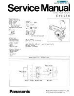
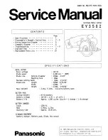
EY3550
Brand: Panasonic Pages: 6
EY3502 - CORDLESS METAL SAW
Brand: Panasonic Pages: 10

EY45A2
Brand: Panasonic Pages: 17

EY3552 - 18V METAL SAW
Brand: Panasonic Pages: 124

EY45A2
Brand: Panasonic Pages: 176

JBGL310
Brand: J.Burrows Pages: 4

COX790125
Brand: Conmetall Meister Pages: 24

ES-09
Brand: Celec Pages: 10

GX-150
Brand: Schulte Pages: 164

ClassicCut CL100
Brand: Rexel Pages: 30

SBC 627 K
Brand: Stiga Pages: 408

B 26 D
Brand: Stiga Pages: 566


