background image


Please read this instructions before operating the device and retain them for future reference. 


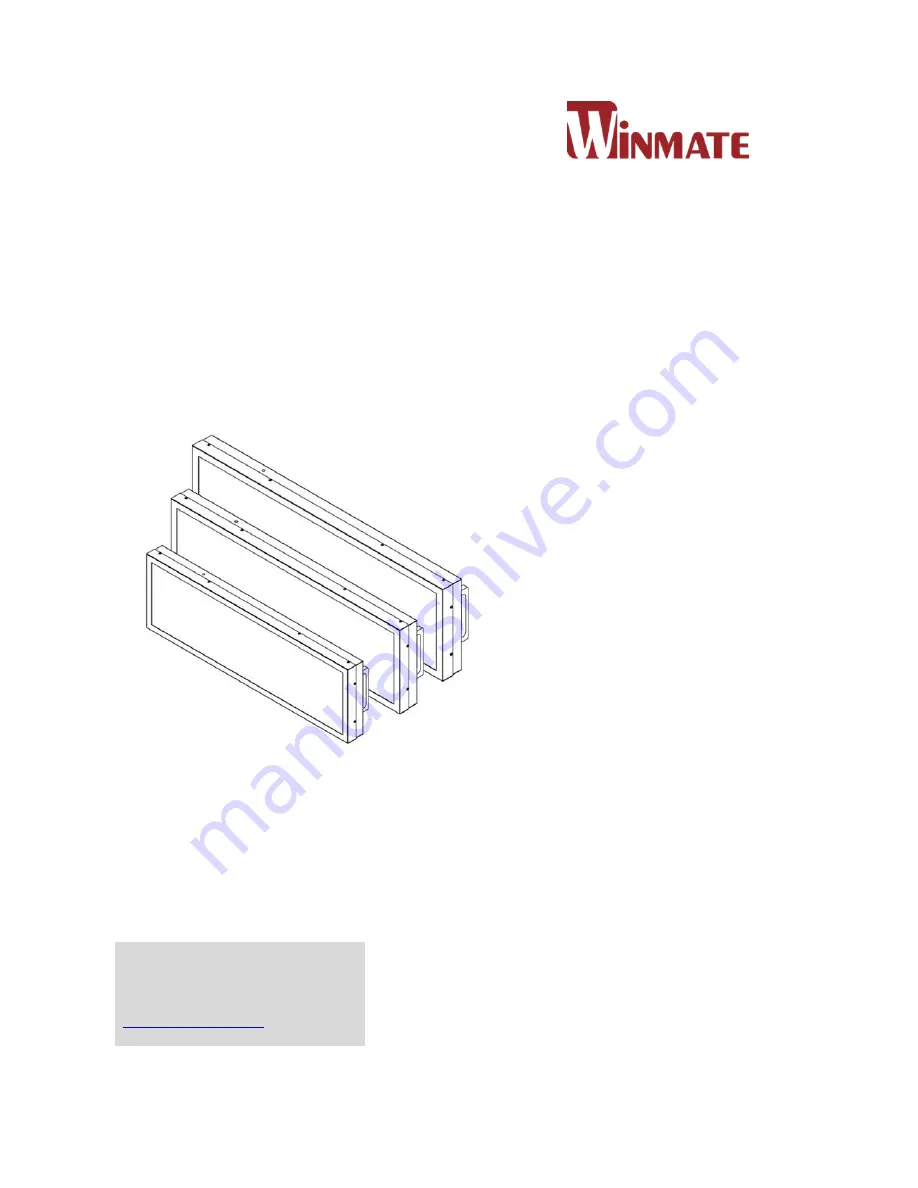
19”/ 27.6”/ 28.6”/ 38”  

Bar-Type 

Chassis Panel PC


Intel® Celeron® Bay Trail-M N2930 1.83 GHz 


W19IB3S-CHA1 

W27IB3S-CHC1 

W28IB3S-CHA2 
W38IB3S-CHA1 


User Manual


V1.1 


For more information on this 
and other Winmate products, 
please visit our website at: 

www.winmate.com


Summary of Contents for W19IB3S-CHA1

Page 1: ...for future reference 19 27 6 28 6 38 Bar Type Chassis Panel PC Intel Celeron Bay Trail M N2930 1 83 GHz W19IB3S CHA1 W27IB3S CHC1 W28IB3S CHA2 W38IB3S CHA1 User Manual V1 1 For more information on th...

Page 2: ...cal Buttons and LED Indicators 19 CHAPTER 2 INSTALLATION 21 2 1 Safety Precautions 21 2 2 Cable Mounting Considerations 21 2 3 VESA Mounting Guide 22 2 4 Powering On 23 2 1 1 AC Adapter Components 23...

Page 3: ...nfiguration 63 4 2 6 Save Exit 65 4 3 Using Recovery Wizard to Restore Computer 67 CHAPTER 5 DRIVER INSTALLATION 70 5 1 Chipset Driver 70 5 2 Graphics Driver 72 5 3 Intel Sideband Fabric Device Intel...

Page 4: ...Applications that are described in this manual are for illustration purposes only We make no representation or guarantee that such application will be suitable for the specified use without further t...

Page 5: ...for technical support if you need additional assistance You may need the following information ready before you call Product serial number Software OS version application software etc Description of c...

Page 6: ...o hardware and explains how to avoid the potential problem Une alerte d attention indique un dommage possible l quipement et explique comment viter le probl me potentiel WARNING AVERTISSEMENT An Elect...

Page 7: ...el exp riment devrait ouvrir ces chassis CAUTION ATTENTION Always ground yourself to remove any static charge before touching the CPU card Modern electronic devices are very sensitive to static electr...

Page 8: ...is correct Position the power cord so that people cannot step on it Do not place anything over the power cord If the equipment is not used for a long time disconnect it from the power source to avoid...

Page 9: ...re afin que l quipement ne se d charge pas sur vous Cover workstations with approved anti static material Use a wrist strap connected to a work surface and properly grounded tools and equipment Use an...

Page 10: ...iate radio frequency energy and if not installed and used in accordance with the instruction manual may cause harmful interference to radio communications Operation of this equipment in a residential...

Page 11: ...cumentation set for the Bar Type Panel PC with Intel Celeron Bay Trail M N2930 1 83 GHz provides information for specific user needs and includes Bar Type Panel PC User Manual contains detailed descri...

Page 12: ...CTION This chapter gives you product overview describes features and hardware specification You will find all accessories that come with the panel PC in the packing list Mechanical dimensions and draw...

Page 13: ...content with one single image or split screens in different places Bar Type can be a perfect choice to replace traditional LED digital signage for applications where the space is limited such as publi...

Page 14: ...sted below are inside your package If any of these items are missing or damaged contact us immediately Standard factory shipment list Bar Type Panel PC User Manual Hardcopy Driver CD Varies by product...

Page 15: ...e that this is a simplified drawing and some components are not marked in detail Please contact our sales representative if you need further product information 1 3 1 Schematics and Dimensions 19 Unit...

Page 16: ...1 IINTRODUCTION 16 1 3 2 Schematics and Dimensions 27 6 No Description No Description Power On button USB 3 0 x 1 USB 2 0 x 1 Reset Button HDMI 1 4a x 1 9 36V DC Terminal Block Phoenix Type RJ 45 LAN...

Page 17: ...INTRODUCTION 17 1 3 3 Schematics and Dimensions 28 6 Unit mm No Description No Description Power On button USB 3 0 x 1 USB 2 0 x 1 Reset Button HDMI 1 4a x 1 9 36V DC Terminal Block Phoenix Type RJ 45...

Page 18: ...IINTRODUCTION 18 1 3 4 Schematics and Dimensions 38 Unit mm No Description No Description Power On button USB 3 0 x 1 USB 2 0 x 1 Reset Button HDMI 1 4a x 1 9 36V DC Terminal Block Phoenix Type RJ 45...

Page 19: ...n Description Reset Press to reset the system Power On Off Press to power on or power off the device LED Indicators Icon LED Indicator Color Description Power LED Off The unit is not connected to the...

Page 20: ...L CHAPTER 2 INSTALLATION 20 INSTALLATION This chapter provides hardware installation instructions and mounting guide for all available mounting options Pay attention to cautions and warning to avoid a...

Page 21: ...you label wiring to all devices in the system 2 2 Cable Mounting Considerations For a nice look and safe installation make sure cables are neatly hidden behind the Panel PC Refer to Chapter 2 section...

Page 22: ...ing hardware to avoid the risk of injury Suivez les instructions de montage et d utilisation recommand le mat riel de montage pour viter le risque de blessure Size VESA Plate Dimensions Screw Hole Dia...

Page 23: ...cover the adapter with paper or other objects that will reduce cooling Do not use the adapter while it is inside a carrying case Do not use the adapter if the cord is damaged There are NO serviceable...

Page 24: ...LE TERRE This product must be grounded Use only a grounded AC outlet Install the additional PE ground wire if the local installation regulations require it If you do not use a grounded outlet while us...

Page 25: ...of power To connect the Panel PC to the source of power 1 Connect a 3 pin terminal block to the connector on the Panel PC 2 Connect the other side of the terminal block to the AC adapter 3 Connect the...

Page 26: ...r Type Panel PC uses COM1 D SUB 9pin connector to connect serial interfaces The connector secured to the enclosure with two screws Refer to Ch 2 Configuring Serial Port Settings of this User Manual fo...

Page 27: ...Serial port settings can be configured for RS 232 RS 422 or RS 485 by jumpers Refer to Ch 2 Configuring Serial Port Settings section of this user manual for the instruction on how to configure COM1 se...

Page 28: ...s Use USB 2 0 connector to connect external devices such as mouse or keyboard to the Panel PC 2 2 6 Ethernet Connector The Bar Type Panel PC supports two RJ45 10 100 1000 Mbps Ethernet interface for c...

Page 29: ...cable to connect the display to the PC system Pin Signal Name Pin Signal Name 1 TMDS_DATA2 2 GND 3 TMDS_DATA2 4 TMDS_DATA1 5 GND 6 TMDS_DATA1 7 TMDS_DATA0 8 GND 9 TMDS_DATA0 10 TMDS_CLOCK 11 GND 12 T...

Page 30: ...he Panel PC 1 Connect the device to the source of power 2 The unit is configured to Power ON when is connected to the power source Refer to Ch 2 Powering On of this User Manual for more details on how...

Page 31: ...ply need a standard cable to make most connections The jumper setting diagram is shown below When the jumper cap is placed on both pins the jumper is SHORT The illustration below shows a 3 pin jumper...

Page 32: ...E DEVICE 32 OPERATING THE DEVICE This chapter provides detailed information on how to operate the device If you have been using touch screen Panel PCs before the interface may look familiar Sections i...

Page 33: ...ing System Flat Stainless P CAP Panel PC support several versions of Windows OS Windows 10 IoT Enterprise Windows Embedded 8 1 Industry Pro Windows Embedded 8 Standard Windows 7 Pro for Embedded Syste...

Page 34: ...efault to CTRL key scroll wheel Move two fingers apart toward each other Rotate No system default unless handled by Application using WM_Gesture API Move two fingers in opposite directions or Use one...

Page 35: ...details To enable watchdog in Watchdog AP follow the instructions below 1 On the right bottom side of the desktop screen click triangle button to show hidden icons 2 Click icon to open Watchdog utili...

Page 36: ...on Watchdog Countdown Time The system automaticity restarts when this countdown time reaches zero Default 10 min Periodically Feed Time To set a cycle time to automatically reset watchdog timer Defaul...

Page 37: ...IOS SETUP 37 AMI UEFI BIOS SETUP BIOS Setup Utility is a program for configuration basic Input Output system settings of the computer for optimum use This chapter provides information on how to use BI...

Page 38: ...F and ON and enter the BIOS again IMPORTANT Updated BIOS version may be published after the manual released Check the latest version of BIOS on the website Run BIOS setup utility for 1 Error message o...

Page 39: ...Help F2 Previous Values F3 Optimized Defaults F4 Save Exit Esc Exit Change Opt Enter Select or execute command Cursor Moves to the previous item Cursor Goes to the next item Cursor Moves to the previ...

Page 40: ...BIOS Setting Description Setting Option Effect System Language Displays the system language English is set up by default Adjustment of the language Set the language in other language The language in t...

Page 41: ...S settings page with caution Any changes can affect the operation of your computer For items marked press Enter for more options Advanced Configuration and Power Interface ACPI settings allow to contr...

Page 42: ...menu PPM Configuration Configures PPM settings Enter Opens submenu Thermal Configuration Configures Thermal Parameters Enter Opens submenu IDE Configuration Configures IDE Parameters Enter Opens subme...

Page 43: ...power requirements You can use the screen to select options of ACPI configuration A description of the selected items will appear on the right side of the screen BIOS Setting Description Setting Opti...

Page 44: ...cted A description of the selected item appears on the right side of the screen For items marked with please press Enter for more options 4 2 2 2 1 Serial Port 1 5 Use these items to set parameters re...

Page 45: ...2 3 GPI0 Port Configuration You can use the screen to change GPI0 Port setting Use these items to set parameters related to PIN3 PIN14 Control 4 2 2 3 Hardware Monitor You can check PC Health Status p...

Page 46: ...4 2 2 4 1 Wake System from S5 with fixed time setting Select Fixed Time to set the system to wake on the specified time Use Navigation Keys to switch among the items Day Hour Minute and Second Type t...

Page 47: ...USER MANUAL CHAPTER 4 AMI UEFI BIOS SETUP 47 4 2 2 4 2 Wake system from S5 after dynamic time setting Select Dynamic Time to set the system to wake on the current time increase minute s...

Page 48: ...ub menu Limit CPUID Maximum Limits CPIID Maximum Disabled Enabled Enable Disable this function Execute Disable Bit Execute Disable Bit Disabled Enabled Enable Disable this function Intel Virtualizatio...

Page 49: ...Setting Description Setting Option Effect CPU C State Report Shows CPU C State Report Enabled Disabled Enable or Disable CPU C state report to OS Max CPU C State Allows to enter power saving mode in o...

Page 50: ...g Description Setting Option Effect Critical Trip Point Specifies the temperature at which the OS will shut down the system 90C 87C 85C 79C 71C 63C 55C 47C 39C 31C 23C 15C Select the disable temperatu...

Page 51: ...nterface Enabled Disabled Enable or disable this function SATA Speed Support Allows forcing the speed limit SATA II ports standard IDE SATA controller chipset Gen1 The maximum speed will be limited to...

Page 52: ...r to increase the speed Serial ATA Port 0 The option turns on or off Port 0 of SATA channels of standard IDE SATA controller chipset Enabled Disabled Turn on Enabled or turn off Disabled Port 0 SATA P...

Page 53: ...select the proper Operating System BIOS Setting Description Setting Option Effect Windows 8 X Allows user to choose the proper OS Enter Use Windows 8 X Windows 7 Allows user to choose the proper OS E...

Page 54: ...USER MANUAL CHAPTER 4 AMI UEFI BIOS SETUP 54 4 2 2 10 CSM Configuration...

Page 55: ...e or disable this function Option ROM Messages Receiving ROM Messages Settings Force BIOS Set ROM messages parameters Network Specifies which Network option ROM is booted UEFI Only UEFI option ROMs ar...

Page 56: ...Option Effect Legacy USB Support User can enable or disable USB port Disable Will keep USB devices available only for EFI applications Enable Enable all the USB devices USB 3 0 Support User can enabl...

Page 57: ......

Page 58: ...ss storage driver support Disable Disables this function Enable Enables this function USB Transfer time out The time out value for control bulk and interrupt transfers 1 Sec 5 Sec 10 Sec 20 Sec Depend...

Page 59: ...AL CHAPTER 4 AMI UEFI BIOS SETUP 59 4 2 2 12 Platform Trust Technology BIOS Setting Description Setting Option Effect fTPM Trusted Platform Module parameters Enabled Disabled Enables or disables this...

Page 60: ...arameters Enabled Disabled Enables or disables this function TXE Firmware Update TXE Firmware Update parameters Enabled Disabled Enables or disables this function TXE EOP Message TXE EOP Message param...

Page 61: ...us Timer settings Enabled Disabled Enables Disables this function Restore AC Power Loss This function allows to set up booting options after a power failure Power on Power off Boot automatically after...

Page 62: ...nistrator password user password and HDD security configuration BIOS Setting Description Setting Option Effect Administrator Password Displays whether or not an administrator password has been set Ent...

Page 63: ...om which to load the operating system BIOS Setting Description Setting Option Effect Setup Prompt Timeout Allows user to configure the number of seconds to stay in BIOS setup prompt screen Enter Set t...

Page 64: ...booting Legacy Only Legacy option is booted UEFI Only UEFI option is booted Boot Option 1 6 Specifies the overall boot order from the available devices Ex Boot Option 1 hard drive Hard drive as the fi...

Page 65: ...Effect Save Changes and Exit This saves the changes to the CMOS and exits the BIOS Setup program Enter YES Save changes Discard Changes and Exit This exits the BIOS Setup without saving the changes m...

Page 66: ...d changes done so far to any of the setup options Enter YES Saves the changes Enter NO Return to the BIOS Setup Main Menu Restore Default Restore load default values for all the setup options Enter YE...

Page 67: ...y procedure Plug in the AC adapter to Bay Trail series computer Make sure the computer stays plugged in to power source during the recovery process Turn on the computer and when the boot screen shows...

Page 68: ...FI BIOS SETUP 68 Wait the recovery process to complete During the recovery process a command prompt will show up to indicate the percent of recovery process complete The system will restart automatica...

Page 69: ...USER MANUAL CHAPTER 5 DRIVER INSTALLATION 69 DRIVER INSTALLATION This chapter describes how to install all necessary drivers...

Page 70: ...VER INSTALLATION This chapter provides guideline to driver installations 5 1 Chipset Driver Step 1 Insert the CD that comes with the motherboard Open the file document Chipset Driver and click infinst...

Page 71: ...71 Step 3 Click Yes to agree the license terms Step 4 Click Next to install the driver Step 5 Software setup progress window will appear click Next to continue Step 6 Click Yes I want to restart this...

Page 72: ...ss Step 3 Carefully read the license terms and click Yes to agree Step 4 Check Readme file information and click Next to install driver Step 5 Click Next to continue Step 6 Windows Security window wil...

Page 73: ...nstall the driver Step 2 Welcome to the setup program window will appear click Next to start the installation Step 3 Carefully read the License Agreement terms and click Yes to agree Step 4 Setup prog...

Page 74: ...the driver Step 2 Welcome to the setup program window will appear click Next to start the installation Step 3 Carefully read the license terms and click Yes to agree Step 4 Confirmation window will a...

Page 75: ...click Next to install the driver Step 4 In the program maintenance window you will see two options available Remove is to remove Intel Networks Connections from your computer and Modify is to make an...

Page 76: ...Echo Cancellation AEC Beam Forming BF and Noise Suppression NS technology Step 1 Insert the CD that comes with the motherboard Open the file document Audio Driver and click Setup exe to install the d...

Page 77: ...ller driver to enable the function Step 1 Locate the hard drive directory where the driver files are stored with the browser or the explore feature of Windows Step 2 Double click the Setup exe from th...

Page 78: ...1 Open the Driver CD included in the package and select Watchdog driver 2 Check message and select Install to begin the installation 3 Wait for installation to complete 4 When installation is complete...

Page 79: ...USER MANUAL CHAPTER 6 TECHNICAL SUPPORT 79 TECHNICAL SUPPORT This chapter includes the directory for technical support...

Page 80: ...s in the package or contact us Also you can download drivers from Winmate Download Center or Winmate File Share Winmate Download Center Go to http www winmate com Support Download Center Digital Signa...

Page 81: ...USER MANUAL APPENDIX A PRODUCT SPECIFICATIONS 81 Product Specifications This section includes product specifications Appendix...

Page 82: ...36 V DC Terminal Block Phoenix Type 9 36 V DC Terminal Block Phoenix Type 9 36 V DC Terminal Block Phoenix Type 9 36 V DC Terminal Block Phoenix Type USB Ports 2 x USB2 0 1 x USB 3 0 1 x USB2 0 1 x US...

Page 83: ...t Drivers Item Driver Windows 7 Windows 8 Windows 10 1 Chipset Driver 2 Graphics Driver 3 Audio Driver 4 Ethernet Driver 5 Intel MBI Driver 6 Intel TXE Driver 7 Watchdog Driver Software Support SDK It...

Page 84: ...Winmate Inc 9F No 111 6 Shing De Rd San Chung District New Taipei City 24158 Taiwan R O C Tel 886 2 8511 0288 Fax 886 2 8511 0211 Email sales winmate com tw Official website www winmate com...

Reviews: