Willcox & Gibbs W542, Instructions Manual
The Willcox & Gibbs W542 exquisite sewing machine requires proper guidance to unleash its full potential. Enhance your sewing experience with our comprehensive Instructions Manual, available for free download on manualshive.com. Discover the endless possibilities of this remarkable machine and bring your creative visions to life.
Share
Download


Reviews:
No comments
Related manuals for W542

4500A
Brand: UnionSpecial Pages: 38

dragon 2000
Brand: SHOWTEC Pages: 20

333-712/02
Brand: Pfaff Pages: 30

Hazer 2000
Brand: BoomToneDJ Pages: 14

CASUAL 845
Brand: Blaupunkt Pages: 68

DDL-5600N Series
Brand: JUKI Pages: 48

LK-1900BN
Brand: JUKI Pages: 115

M-920
Brand: Muratec Pages: 41

F5.0L-PSG
Brand: Foamit Pages: 4
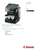
Saeco Via Veneto RI9345/11
Brand: Philips Pages: 2
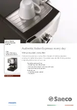
Saeco Poemia HD8325/79
Brand: Philips Pages: 2
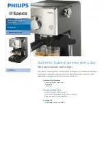
Saeco Poemia HD8325/47
Brand: Philips Pages: 3
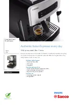
Saeco Poemia HD8425/01
Brand: Philips Pages: 3

Embroidery Machine
Brand: eMotions Pages: 42

28 Slim Gem
Brand: AMS Pages: 51

714
Brand: Baumfolder Pages: 12

i28BTL
Brand: Ice Pages: 39

ZJ8800A
Brand: ZOJE Pages: 43


