background image

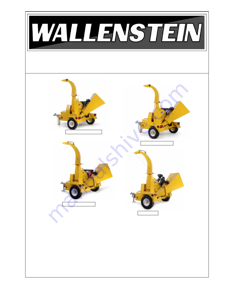
TRAILER WOOD CHIPPER

MODEL


BXT4213, BXT4214su, BXT4224, 

BXT4228su, BXT6224, BXT6228su & 

BXT6238

OPERATOR'S MANUAL

BY 

EMB MFG INC.

PRINTED IN CANADA

Rev: 290512                                                                                                              PART NUMBER: Z97033

EMB Manufacturing Inc.

4144 Boomer Line · St. Clements, On · N0B 2M0 · Canada

Ph: (519) 699-9283 · Fax: (519) 699-4146

 www.embmfg.com

BXT4213 / BXT4214su

BXT4224 / BXT4228su

BXT6224 / BXT6228su

BXT6238

Summary of Contents for BXT4213

Page 1: ...T6228su BXT6238 OPERATOR S MANUAL BY EMB MFG INC PRINTED IN CANADA Rev 290512 PART NUMBER Z97033 EMB Manufacturing Inc 4144 Boomer Line St Clements On N0B 2M0 Canada Ph 519 699 9283 Fax 519 699 4146 www embmfg com BXT4213 BXT4214su BXT4224 BXT4228su BXT6224 BXT6228su BXT6238 ...

Page 2: ...MANUAL START 21 4 5 2 GAS ENGINE ELECTRIC START 22 4 6 BALL COUPLER 23 4 7 MACHINE SET UP 24 4 8 FIELD OPERATION 25 4 8 1 PREPARE 25 4 8 2 STARTING PROCEDURE 26 4 8 3 STOPPING 26 4 8 4 EMERGENCY STOPPING 26 4 8 5 CHIPPING OPERATION 27 4 8 6 UNPLUGGING 28 4 8 7 SEVERE PLUG 28 4 8 8 REFUELLING 29 4 8 9 SAFETY CURTAINS 29 4 8 10 OPERATING HINTS 29 5 TRANSPORTING 30 6 STORAGE 31 6 1 PLACING IN STORAGE...

Page 3: ...e contact your local engine dealer Under no circumstances will the manufacturer be liable for any consequential damage or expense of any kind including loss of profits The manufacturer is under no circumstances liable for tow vehicle of any kind The manufacturer is not liable for the maintenance of the product This warranty is extended only to the original purchaser and is not transferable Warrant...

Page 4: ...perator s Manual have been received by me and I have been thoroughly instructed as to care adjustments safe operation and applicable warranty policy This form must be filled out by the dealer and signed by both the dealer and the customer at the time of delivery Customer s Name Dealer Name Address Address City State Province Code City State Province Code Phone Number Phone Number Contact Name Mode...

Page 5: ...The serial number plate is located where indicated Model BXT6238 is shown but the location of the plate is the same across all models covered in this manual Please mark the numbers in the spaces provided for easy reference SERIAL NUMBER LOCATION Model Number _____________________________________________________ Chipper Serial Number ______________________________________________ Engine ...

Page 6: ...anual covers the Wallenstein Trailer Wood Chipper BXT4213 BXT4224 BXT6224 with Honda engines and BXT4214su BXT4228su BXT6228su with Subaru engines and BXT6238 with a Kohler engine Use the Table of Contents or Index as a guide to locate required information Keep this manual handy for frequent reference and to pass on to new operators or owners Call your Wallenstein dealer or the Distributor if you ...

Page 7: ...699 9283 or Fax 519 699 4146 DANGER Indicates an imminently hazardous situation that if not avoided will result in death or serious injury This signal word is to be limited to the most extreme situations typically for machine components which for func tional purposes cannot be guarded WARNING Indicates a potentially hazardous situation that if not avoided could result in death or serious injury an...

Page 8: ...n be avoided A person who has not read and understood all using and safety instructions is not qualified to use the machine An untrained operator exposes himself and bystanders to possible serious injury or death Do not modify the equipment in any way Unauthorized modification may impair the function and or safety and could affect the life of the equipment Think SAFETY Work SAFELY 1 Read and under...

Page 9: ...owed to work with this equipment Do not allow persons to use or assemble this unit until they have read this manual and have developed a thorough understanding of the safety precautions and of how it works Review the safety instructions with all users annually 6 This equipment is dangerous to children and persons unfamiliar with its operation The operator should be a responsible properly trained a...

Page 10: ...your engine 6 Train all new personnel and review instruc tions frequently with existing workers Be certain only a properly trained and physically able person will use the machinery A person who has not read and understood all using and safety instructions is not qualified to use the machine An untrained operator exposes himself and bystanders to possible serious in jury or death If the elderly are...

Page 11: ...good operating condition 7 Ensure that all safety shielding and safety signs are properly installed and in good condi tion 2 6 MAINTENANCE SAFETY 1 Good maintenance is your responsibility Poor maintenance is an invitation to trouble 2 Follow good shop practices Keep service area clean and dry Be sure electrical outlets and tools are properly grounded Use adequate light for the job at hand 3 Make s...

Page 12: ...embly installation operation main tenance repairing unplugging or moving 9 Turn machine off stop and disable engine remove ignition key and place in your pocket set park brake and wait for all moving parts to stop before servicing adjusting repairing or unplugging 10 Do not run machine inside a closed building to prevent asphyxiation from engine exhaust 11 Use care when feeding material into chipp...

Page 13: ...position and crank until engine starts 15 DO NOT strike flywheel with a hard object or metal tool as this may cause flywheel to shat ter in operation Use proper tools to service engine 16 DO NOT operate engine without a muffler Inspect periodically and replace if necessary If engine is equipped with a muffler deflector inspect periodically and replace if necessary with correct deflector 17 DO NOT ...

Page 14: ...r bat teries 4 Do not tip batteries more than 45 to avoid electrolyte loss 5 To avoid injury from spark or short circuit dis connect battery ground cable before servicing any part of the electrical system 2 13 TRANSPORT SAFETY 1 Comply with Provincial state and local laws governing safety and transporting of machin ery on public roads 2 Check that all the lights reflectors and other lighting requi...

Page 15: ... anyone else to use this chipper until such information has been reviewed Annually review this information before the season start up Make these periodic reviews of SAFETY and OPERATION a standard practice for all of your equipment We feel that an untrained operator is unqualified to use this machine A sign off sheet is provided for your record keeping to show that all personnel who will be workin...

Page 16: ...are shown in the illustrations that follow Model BXT6238 is illustrated but indicates the general location of the various safety signs Good safety requires that you familiarize yourself with the various safety signs the type of warning and the area or particular function related to that area that requires your SAFETY AWARENESS Think SAFETY Work SAFELY Z94006 Z94007 Z94012 Z94013 Z94008 Z94007 x 4 ...

Page 17: ...are shown in the illustrations that follow Model BXT6238 is illustrated but indicates the general location of the various safety signs Good safety requires that you familiarize yourself with the various safety signs the type of warning and the area or particular function related to that area that requires your SAFETY AWARENESS Think SAFETY Work SAFELY Z94120 x 4 Z94116 x 1 Z94127 x 1 Z94117 x 3 Z9...

Page 18: ...hat safety glasses safety shoes and gloves are recommended during assembly installation operation ad justment maintaining repairing or plugging Do not allow long hair loose fitting clothing or jewellery to be around moving parts Turn machine off stop and disable en gine remove ignition key and place in your pocket set park brake and wait for all mov ing parts to stop before servicing adjusting rep...

Page 19: ...he material An engine is mounted on the frame to drive the rotor Power is transmitted through a centrifugal clutch on the engine output shaft and through a V belt drive system Fig 7 PRINCIPLE COMPONENTS Centrifugal Clutch Gas Tank Access Flap Swivel Jack Manual Tube Double B V Belt Ledger Blade Upper Rotor Housing Rotor Plate Twig Breaker Rotor Blade Hopper Transport Latch Storage Belt Guard Engin...

Page 20: ... each opera tor reads and understands the using procedures and all related safety precautions outlined in this section A pre operation checklist is provided for the operator It is important for both the personal safety and maintaining good mechanical condition that this checklist is followed Before operating Wood Chipper and each time thereafter the following areas should be checked off 1 Lubricat...

Page 21: ... it will return to the RUN position Fuel Shut Off Valves Each engine is equipped with a valve between the fuel tank and the carburettor Slide the fuel valve toward the block to turn ON and away to turn OFF Turn the fuel OFF when not in use or when transporting Throttle This lever controls the engine RPM Move the lever side to side Always run at maximum throttle while operating Choke The choke cont...

Page 22: ... starts and it will return to the RUN position Choke Honda Kohler Honda This push pull knob controls the position of the choke Pull the knob out to close the choke for starting when the engine is cold Push the knob in to open the choke as the engine warms Always push the knob in fully in when operating the machine Kohler This left right slider controls the position of the choke Slide the choke to ...

Page 23: ...stall the snapper pin to secure the latch d BXT4213 BXT4214su Pull out the snap per pin and pull up to place stand in its stowed position Replace snapper pin e BXT4224 BXT6224 BXT4228su BXT 6228su BXT6238 Crank the swivel jack up pull out the snapper pin and swivel the stand into its stowed position Replace snapper pin 6 Attach the safety chain securely to the tow frame to prevent unexpected separ...

Page 24: ...e 1 Use the tow unit to position the Wood Chipper at the work site 2 The chipper can be used as a stand alone or if you require more stability leave your chipper attached to the tow vehicle IMPORTANT Position the machine so the prevail ing wind breeze blows the exhaust gases fumes away from the opera tor s station Fig 12 BATTERY CABLE typical Stowed Position Working Position 4 Check the battery ca...

Page 25: ...chipper If foreign material enters chipper stop machine turn engine off and place ignition key in your pocket and wait for all moving parts to stop before removing mate rial and or unplugging Inspect machine for damaged or loose parts before resuming work Never use alcoholic beverages or drugs which can hinder alertness or coordination while operating this equipment Consult your doctor about opera...

Page 26: ...anual Start BXT4213 BXT4214su Turn the ignition switch to on Grasp the T bar on the pull cord firmly and pull the rope sharply to start the engine Fig 15 STARTING STOPPING h Run the engine for a few minutes to allow it to warm i Gradually open the choke j Turn the discharge head to its desired posi tion k Slowly increase the engine speed to engage the centrifugal clutch l Increase throttle setting...

Page 27: ...g work 4 8 5 CHIPPING OPERATION Fig 16 OPERATING Caution and care should be exercised when feeding material into the feeder Do not reach into the hopper past the curtain barrier a Before beginning to feed ensure the motor warmed up and the rotor is up to speed b Slowly slide the wooden material into the feed hopper and move it into the rotor c Do not force the material into the rotor as the materi...

Page 28: ...NING Machine is shown with guard removed or rotor cover opened for illustrative purposes only Do not operate machine with guard removed or cover opened 4 8 7 SEVERE PLUG a Clear the area of bystanders especially small children b Stop the engine remove the ignition key and place it in your pocket or remove spark plug wire and wait for all moving parts to stop before unplugging c Loosen the feed hop...

Page 29: ...g Replace the curtain if torn damaged or missing to minimize the chance of material coming out of the feed hopper 4 8 10 OPERATING HINTS a Keep the working area clean and free of debris to prevent slipping or tripping Operate only on level ground b Do not place hands or any body parts into the feed hopper during operation Use a stick or branch to push material into the rotor when it goes past the ...

Page 30: ...ons 1 Clear the area of bystanders especially small children 2 Check that all the lights and reflectors re quired by the highway authorities are in place clean and working 3 Insure that the machine is securely attached to the pick up with a mechanical retainer through the ball hitch mechanism Always use safety chains crossed between the truck and machine 5 TRANSPORTING 4 Do not allow riders 5 Neve...

Page 31: ...o dry the moisture from inside the machine 6 Turn fuel valve off 7 Move the feed hopper up and lock 8 Touch up all paint nicks and scratches to pre vent rusting 9 Remove ignition key and store in a secure place 10 Remove the battery and store it in a cool dry area on wooden blocks or a wooden pallet Charge it monthly to maintain an adequate charge 11 It is best to store the machine inside If that ...

Page 32: ...ions are properly secured to ensure unit is in a safe condition When completing a maintenance or service function make sure all safety shields and de vices are installed before placing unit in serv ice 7 SERVICE AND MAINTENANCE 7 1 SERVICE 7 1 1 FLUIDS AND LUBRICANTS 1 Grease Use an SAE multipurpose high temperature grease with extreme pressure EP perform ance Also acceptable is an SAE multipur po...

Page 33: ... manual for specific service instructions Fuel check daily or every 8 hrs Drain fuel if not being used for long peri ods of time Belt drive Check ten sion daily adjust every 100 hrs Rotor bearings grease with one shot of grease front and rear every 100 hours or annually Ledger blade check daily test sharpness every 50 hrs Twig Breaker check every 8 hrs Rotor blades check daily test sharpness every...

Page 34: ... 50 Hours or Annually 100 Hours or Annually T w i g B r e a k e r C h o p B l o c k B l a d e s K n i v e s S e c u r e f a s t e n e r s B e l t D r i v e P u l l e y A l i g n m e n t I n s p e c t L u b r i c a t e h i n g e s a n d p i v o t p o i n t s L e d g e r B l a d e S h r e d d e r K n i v e s P T O D r i v e l i n e R o t o r B e a r i n g s B e l t D r i v e C l e a n M a c h i n e ...

Page 35: ...sed 2 Remove the 4 bolts that secure the belt guard and the 3 bolts that secure the up per belt guard to the chipper and remove the guards 3 Loosen do not remove the 4 x bolts that hold the engine mount to the main frame located at the bottom of the motor mount 4 Turn the belt tensioning bolt counter clock wise until belt is loose enough to remove then remove the belt see figure 24 5 Replace with ...

Page 36: ...ion switch is off and the fuel valve is closed 2 Remove the 4 bolts that hold the belt guard to the chipper remove the belt guard 3 Check the tension by pushing on the belt with your fore finger and measure its defection Drive belt should deflect no more than 1 2 to 5 8 13 mm to 16 mm 4 If the belt requires adjustment lift and secure the hopper loosen do not remove the 4 x bolts that hold the engi...

Page 37: ... straight edge and the clutch or the sheave measure the gap A 7 If there is more than 1 32 8mm offset then adjustment is required 8 To adjust alignment a Loosen the set screw on the bushing at tached to rotor sheave b Remove the 3 hex bolts on the bushing and thread them into the tapped holes on the bushing c Tighten the hex bolts progressively with 1 4 turns until bushing is free from the sheave ...

Page 38: ...s it meets the stationary blade Be sure to tighten the blade mounting bolts to their specified torque when re installing the blades to the rotor 1 Ensure the engine is off ignition switch is off and the fuel valve is closed 2 Remove the bolt that secures the upper rotor housing and carefully open the rotor housing 3 Manually rotate chipper rotor plate so that the blade is fully exposed 4 Remove th...

Page 39: ...pper clearance setting gauge available from your dealer see accessories 5 Tighten down bolts as specified in the torque chart Ledger Blade Fig 27 LEDGER BLADE Ledger Blade Bolts Twig Breaker The Twig Breaker is a breaker tab located on side of the lower rotor housing The discharge paddle passes around the twig breaker and helps to break the material into smaller pieces and turn it into mulch Inspe...

Page 40: ... to specified angle and check that blade is installed properly Ensure machine is off Obstructed discharge Clear debris from discharge chute Ensure machine is off Broken or missing blade Replace broken missing blade Ensure machine is off Rotor may be bent Check rotor to see if it wobbles Replace rotor Ensure machine is off call technician for repair Obstructed discharge Clear debris from discharge ...

Page 41: ...ght 197 lb 89 4 kg Feeding System Feed Mounting System Dimensions Hopper Folded L x W x H 86 L x 75 W x 88 H 203cm x 191cm x 224cm Hopper Opening 25 x 25 64cm x 64cm Discharge Hood Rotation Discharge Hood Height 88 224cm Rated RPM Weight 785 lb 356 kg 825 lb 374 kg 1365 lb 1385 lb 619 kg 628 kg Tire Size 20 5 x 8 10 72 183cm 360 degrees Belt drive centrifugal clutch 4 Dia 10 1 cm Max 10 slab 25 4c...

Page 42: ... 19 33 53 80 115 160 290 420 630 17 36 63 100 155 220 305 540 880 1320 12 27 45 75 115 165 220 400 650 970 METRIC TORQUE SPECIFICATIONS 8 8 N m lb ft Bolt Torque Bolt Diameter A 10 9 N m lb ft M3 M4 M5 M6 M8 M10 M12 M14 M16 M20 M24 M30 M36 5 3 6 10 25 50 90 140 225 435 750 1495 2600 4 2 2 4 7 18 37 66 103 166 321 553 1103 1917 1 8 4 5 9 15 35 70 125 200 310 610 1050 2100 3675 1 3 3 3 7 11 26 52 92...

Page 43: ... com and click on Parts and Manuals to download the latest parts manual for you model splitter then call your dealer to order For BXT Series Chippers An easy and accurate way of setting the critical clearancesbetweentheledgerbladeandtherotor chipper blade 1012L269 LEDGER CLEARANCE SETTING GAUGE 1012L269 ...

Page 44: ... K KOHLER 6 KOHLER CH980 22 32 L LATCH 30 LEDGER BLADES 39 M MANUAL START 26 O OIL 32 OPERATING 27 ORIENTATION 6 OSHA 15 P POSITION 24 PPE 25 PROTECTIVE GEAR 8 R ROTOR BLADE 19 38 S SAFETY 7 SAFETY CURTAIN 27 SAFETY STANDARDS 15 SERVICE ILLUSTRATION 33 SERVICE RECORD 34 SEVERE PLUG 28 SHARPEN 38 SHEAVE 37 SIGNAL WORDS 7 SPECIFICATIONS 41 STARTING ROPE 21 STOWED 24 S cont STRAIGHT EDGE 37 SUBARU 6 ...

Reviews: