background image

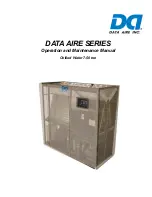
MODEL YHAU-CGN/H

120-1600 TON

422-5626 KW

Direct Fired Absorption Chiller-Heater

Installation, Operation, Maintenance

Form 155.32-ICOM2.EN.UL (1018)

Issue Date: October 1, 2018 

New Release

LD26829

Summary of Contents for YHAU-CGN

Page 1: ...MODEL YHAU CGN H 120 1600 TON 422 5626 KW Direct Fired Absorption Chiller Heater Installation Operation Maintenance Form 155 32 ICOM2 EN UL 1018 Issue Date October 1 2018 New Release LD26829...

Page 2: ...ed rigging installation and operating service personnel It is expected that these individuals possess independent training that will enable them to perform their assigned tasks properly and safely It...

Page 3: ...y of these documents to the equipment If there is any question regarding the applicability of these documents rigging lifting and operating service personnel should verify whether the equipment has be...

Page 4: ...4 3 4 4 6 9 4 9 3 52 4GZ XGR GY 26 OKYKR 5OR 1 1KXUYKTK 8 453 4 2 6 8 453 4 2 6 8 453 4 2 6 8 8 4 9ZGTJGXJ 5TK 9O K 2GXMKX UXQ HYUXVZOUT NORRKX 9 0 22 4 453 4 2 8 9 5 8 8 5 8 25 36 4 4UTK 4U NKGZ XKIU...

Page 5: ...HTG 19 Low Temperature Generator LTG 19 Condenser 20 Crystallization 20 Why Does Crystallization Occur 20 SECTION 3 HANDLING STORAGE INSTALLATION AND REASSEMBLY 21 Inspection 21 Inspection Window 21...

Page 6: ...ller Heater 86 Interlocking Procedure 86 SECTION 6 OPERATION 89 YHAU CGN H Control Center 89 Common Items 89 Change Numeric Values 90 Operating Status 92 Solution Analysis Control Panel Parts Replacem...

Page 7: ...ant Blow Down and Diluting Method 137 Decrystallization Method 137 Indications of Crystallization 137 Decrystallization 138 Precautions for Decrystallization 139 Maintenance Items 139 Refrigerant Pump...

Page 8: ...Input Wiring 70 Figure 27 Display Analog Output Wiring 71 Figure 28 Output Wiring 72 Figure 29 Interior of Control Panel 72 Figure 30 External Connection Terminal Details 73 Figure 31 Remote Transmis...

Page 9: ...r only 131 Figure 65 YHAU CGN H Direct Fired Chiller Heater with Evaporator Heating Flow Diagram Simultaneous Cooling and Residential Hot Water Only 132 Figure 66 YHAU CGN H Direct Fired Chiller Heate...

Page 10: ...System 79 Table 27 Cable Diagram RS 422 RS485 79 Table 28 Communication Specifications 81 Table 29 Rotary Pump Rotation 84 Table 30 Liquid Level Gauges Sight Glass 85 Table 31 Failure List 109 Table 3...

Page 11: ...by incorrect in stallation commissioning operation or maintenance resulting from a failure to follow the procedures and instructions detailed in this manual WARRANTY Johnson Controls warrants YHAU CG...

Page 12: ...r Safety Heating and Cooling Equipment UL 508A Industrial Control panel NFPA70 National Electrical Code NFPA79 Electrical Standard for Industrial Machinery The unit must be grounded No installation or...

Page 13: ...hine may start automatically without prior warning Caution Hot surface Warning Safety relief valve may discharge gas or liquid without prior warning Warning Risk of electric shock General attention sy...

Page 14: ...FORM 155 32 ICOM2 EN UL ISSUE DATE 1 10 2018 14 JOHNSON CONTROLS THIS PAGE INTENTIONALLY LEFT BLANK...

Page 15: ...consists of the following components evaporator absorber condenser generator solution heat exchangers to heighten the cycle efficiency pumps to circulate the refrigerant and solution in the cycle purg...

Page 16: ...GN H 120 300EX H S and 360EX 1600EXW3 H S A B C D E F G H I J K L ITEM COMPONENTS ITEM COMPONENTS A G B H C I D J E K F L UUROTM GZKX 5 ZRKZ UUROTM GZKX TRKZ UTJKTYKX NORRKJ UZ GZKX TRKZ 2U KSVKXGZ XK...

Page 17: ...ant to flash from a liquid to a vapor The temperature at which this happens depends on the evaporator shell pressure which is dictated by the absorber section of the chiller heater The refrigerant vap...

Page 18: ...rrosion the risk of crystallization and improves efficiency in conjunction with other advanced components described later in this section The two evaporators are in series with respect to the chilled...

Page 19: ...AU s high temperature generator has the unique liquid tube design in which the dilute LiBr solution coming from the high temperature heat exchanger is inside the tubes The products of combustion exhau...

Page 20: ...higher solution temperatures are maintained Special measures do have to be taken before the unit is shut down so that the solution is sufficiently diluted in all areas of the unit to prevent crystalli...

Page 21: ...ative All damage or possible damage must be reported to the transportation company For further details see SECTION 5 COMMISSIONING INSPECTION WINDOW The inspection window of the exhaust gas duct or ch...

Page 22: ...ntative Measures CAUTION Gas pipe fittings must be installed by a qualified contractor Defective gas piping can cause an oxygen deficient accident or a fire PROBLEM PREVENTATIVE MEASURE Freezing of re...

Page 23: ...below Use care not to apply shock to the machine The machine is a high vacuum vessel containing a corrosive solution Use diligence in protecting the machine as repair is labor intensive and costly Be...

Page 24: ...uum vessel containing a corrosive solution Use diligence in protecting the machine as repair is labor intensive and costly When a skid base is used to move the machine on rollers secure the skid base...

Page 25: ...support on the main shell of the body as shown below If using a high temperature generator use secondary jack up support Operate the front and rear jacks alternately Do not jack up the machine more th...

Page 26: ...unit INDOOR AND OUTDOOR INSTALLATION This chiller heater is designed to be used indoors Exposure to the elements can compromise the integrity of the thermal insulation Minimum allowable temperature f...

Page 27: ...s service office for inspection and maintenance of the unit Improper inspection and maintenance can not only cause a machine malfunction but also injury Keep the chilled hot water and cooling water un...

Page 28: ...umstances Be careful not to compromise the integrity of the vessel Prior to welding verify that the electrical system is grounded properly Failure to do this can result in electrical shock injury and...

Page 29: ...ted at 7 0 PSIG 2 0 PSI 48 2 kPa 13 8 kPa The size of the rupture disc will depend on the chiller capacity The rupture disk will protect the chiller s integrity should there ever be a tube rupture or...

Page 30: ...piping material Johnson Controls recommends carbon steel The relief piping must be fabricated and constructed in accordance with piping best practices Follow any local codes if applicable governing th...

Page 31: ...elief device operates shall be considered The sizing of the discharge line for above condition must be based on the sum of each rupture disk outlet area in addition to the pressure drop allowance thro...

Page 32: ...T OUTLET 120 300EX H S A ODD PASS B A ODD PASS B B A EVEN PASS A EVEN PASS A 360EX H S 1600EXW3 H S B ODD PASS A B ODD PASS A B A EVEN PASS B EVEN PASS B ITEM DESCRIPTION YHAU CGN H 120 300EX H S ITEM...

Page 33: ...ractor or customer See Figure 13 on page 33 to plan the fuel supply piping from oil storage tank to chiller heater Figure 13 Oil System NOTE Install an oil gauge near the chiller heater The oil servic...

Page 34: ...is installed side by side with a boiler etc provide the chillers with separate flues to prevent the back flow of exhaust gas to the machine that is not operating When installing an assembly gas duct u...

Page 35: ...agram NOTE 1 The smokestacks box option and the flue and instruments after the points of con nection with the flue are outside the scope of delivery 2 Insulate the flue on the basis of 662 F to protec...

Page 36: ...r install the insulation in a way to permit removing the front sides and rear separately In addition make a removable part around the rear end for inspection of the temperature relay and sensor Table...

Page 37: ...155 32 ICOM2 EN UL SECTION 3 HANDLING STORAGE INSTALLATION AND REASSEMBLY ISSUE DATE 1 10 2018 JOHNSON CONTROLS 37 Figure 16 Interior of Control Panel MM Figure 17 Exterior of Control Panel LD27466 LD...

Page 38: ...FORM 155 32 ICOM2 EN UL ISSUE DATE 1 10 2018 38 JOHNSON CONTROLS THIS PAGE INTENTIONALLY LEFT BLANK...

Page 39: ...n in the table below are the allowable ranges for each parameter Not all combinations are possible Please check with your Johnson Controls Service Center to see if your temperature differential is pos...

Page 40: ...565 18 4 44 974 20 4 72 312 32 8 42 329 19 2 46 738 21 2 75 619 34 3 600EXS 45 415 20 6 50 265 22 8 80 028 36 3 46 077 20 9 50 927 23 1 82 012 37 2 700EXS 50 265 22 8 55 557 25 2 89 728 40 7 50 927 23...

Page 41: ...3 46 958 21 3 74 296 33 7 44 313 20 1 48 722 22 1 77 603 35 2 600EXH 47 840 21 7 52 470 23 8 82 232 37 3 48 502 22 53 131 24 1 84 437 38 3 700EXH 52 911 24 58 202 26 4 92 374 41 9 53 572 24 3 58 863 2...

Page 42: ...32 1 17 500EX H S 120 81 3 42 18 34 5 59 7 84 2 39 10 18 3 1 14 76 4 5 387 5 36 172 22 16 21 19 0 6 44 14 1 25 560EX H S 150 97 4 28 19 98 6 09 7 84 2 39 10 18 3 1 16 4 5 419 79 39 182 99 17 22 95 0...

Page 43: ...27 1 48 700EX H S 252 22 7 15 24 25 7 39 9 78 2 98 10 18 3 11 20 67 6 3 473 62 44 215 28 20 27 9 0 79 56 86 1 61 800EX H S 252 22 7 15 26 55 8 09 10 73 3 27 10 18 3 11 22 97 7 559 73 52 247 57 23 31 0...

Page 44: ...11 1 68 0 2 2 5 2 24 0 500 EX H S AC460V 3Ph 60Hz 40 A 125 A 5 5 11 1 68 0 2 2 5 2 24 0 560 EX H S AC460V 3Ph 60Hz 40 A 125 A 5 5 11 1 68 0 2 2 5 2 24 0 600 EX H S AC460V 3Ph 60Hz 45 A 125 A 5 5 11 1...

Page 45: ...S 0 4 1 5 4 7 0 75 1 8 9 0 5 60 8 6 79 8 21 2 17 0 35 1 42 9 5 560 EX H S 0 4 1 5 4 7 0 75 1 8 9 0 5 60 8 6 79 8 21 2 17 0 35 1 42 9 5 600 EX H S 0 4 1 5 4 7 0 75 1 8 9 0 7 46 12 0 79 8 21 2 17 0 39...

Page 46: ...5 5 14 2 60 0 2 2 6 1 23 0 700 EX H S AC460 3P 60Hz 35 A 125 A 5 5 14 2 60 0 2 2 6 1 23 0 800 EX H S AC460 3P 60Hz 35 A 125 A 5 5 14 2 60 0 2 2 6 5 20 3 900 EX H S AC460 3P 60Hz 45 A 125 A 5 5 14 2 6...

Page 47: ...56 4 20 8 16 7 5 700 EX H S 0 4 1 5 4 7 0 75 1 8 9 0 3 73 6 0 56 4 20 8 16 7 5 800 EX H S 0 4 1 5 4 7 0 75 1 8 9 0 3 73 6 0 56 4 20 8 16 7 5 900 EX H S 1 3 3 9 14 0 0 75 1 8 9 0 7 46 12 0 78 9 27 3 2...

Page 48: ...5 29 982 83 13 6 19 731 35 8 95 1200EXW3H 29 982 83 13 6 21 980 06 9 97 33 069 3 15 20 348 64 9 23 1300EXW3H 32 848 84 14 9 22 707 59 10 3 34 171 61 15 5 23 589 43 10 7 1400EXW3H 34 612 53 15 7 24 030...

Page 49: ...3 56 8 13 26 896 36 12 2 17 703 1 8 03 1200EXW3S 27 116 83 12 3 19 863 63 9 01 29 762 37 13 5 18 408 58 8 35 1300EXW3S 29 541 91 13 4 20 370 69 9 24 30 644 22 13 9 21 164 35 9 6 1400EXW3S 31 305 6 14...

Page 50: ...4 8 4 59 1 4 6 56 2 7 496 3 4 560EXH 19 36 5 9 7 55 2 3 9 19 2 8 24 471 11 1 18 7 5 7 5 25 1 6 3 61 1 1 5 953 2 7 16 73 5 1 4 59 1 4 6 56 2 7 716 3 5 600EXH 21 6 4 8 2 2 5 9 19 2 8 26 896 12 2 20 34 6...

Page 51: ...1 1 1 7 055 3 2 19 36 5 9 4 59 1 4 6 56 2 9 921 4 5 800EXH 25 92 7 9 8 2 2 5 9 19 2 8 38 801 17 6 25 26 7 7 5 25 1 6 3 61 1 1 7 716 3 5 21 65 6 6 5 58 1 7 9 19 2 8 15 432 7 900EXWH 23 95 7 3 8 53 2 6...

Page 52: ...SECTION 4 TECHNICAL DATA FORM 155 32 ICOM2 EN UL ISSUE DATE 1 10 2018 52 JOHNSON CONTROLS Figure 18 Split Drawing LD23000 Main Shell Unit W1 L1 H1 HX Unit W2 L2 H2 HG Unit W3 L3 H3...

Page 53: ...59 1 4 6 56 2 7 496 3 4 560EXS 19 36 5 9 7 55 2 3 9 19 2 8 24 471 11 1 18 7 5 7 5 25 1 6 3 61 1 1 2 646 1 2 16 73 5 1 4 59 1 4 6 56 2 7 716 3 5 600EXS 21 6 4 8 2 2 5 9 19 2 8 26 896 12 2 20 34 6 2 5...

Page 54: ...65 6 6 5 58 1 7 9 19 2 8 15 432 36 7 800EXS 23 95 7 3 8 53 2 6 9 19 2 8 45 415 22 20 6 21 98 6 7 5 91 1 8 3 61 1 1 3 747 86 1 7 19 36 5 9 5 58 1 7 9 19 2 8 14 991 43 6 8 900EXWS 26 25 8 8 53 2 6 9 19...

Page 55: ...FORM 155 32 ICOM2 EN UL ISSUE DATE 1 10 2018 JOHNSON CONTROLS 55 THIS PAGE INTENTIONALLY LEFT BLANK...

Page 56: ...SECTION 4 TECHNICAL DATA FORM 155 32 ICOM2 EN UL ISSUE DATE 1 10 2018 56 JOHNSON CONTROLS Figure 19 Power Wiring LD27462...

Page 57: ...FORM 155 32 ICOM2 EN UL SECTION 4 TECHNICAL DATA ISSUE DATE 1 10 2018 JOHNSON CONTROLS 57 LD27463...

Page 58: ...SECTION 4 TECHNICAL DATA FORM 155 32 ICOM2 EN UL ISSUE DATE 1 10 2018 58 JOHNSON CONTROLS Figure 20 Power Supply Wiring...

Page 59: ...FORM 155 32 ICOM2 EN UL SECTION 4 TECHNICAL DATA ISSUE DATE 1 10 2018 JOHNSON CONTROLS 59 LD27465...

Page 60: ...SECTION 4 TECHNICAL DATA FORM 155 32 ICOM2 EN UL ISSUE DATE 1 10 2018 60 JOHNSON CONTROLS Figure 21 Power Supply Wiring LD27470...

Page 61: ...FORM 155 32 ICOM2 EN UL SECTION 4 TECHNICAL DATA ISSUE DATE 1 10 2018 JOHNSON CONTROLS 61 LD27471...

Page 62: ...SECTION 4 TECHNICAL DATA FORM 155 32 ICOM2 EN UL ISSUE DATE 1 10 2018 62 JOHNSON CONTROLS Figure 22 PLC Input Wiring...

Page 63: ...FORM 155 32 ICOM2 EN UL SECTION 4 TECHNICAL DATA ISSUE DATE 1 10 2018 JOHNSON CONTROLS 63...

Page 64: ...SECTION 4 TECHNICAL DATA FORM 155 32 ICOM2 EN UL ISSUE DATE 1 10 2018 64 JOHNSON CONTROLS Figure 23 PLC Input Wiring LD27476...

Page 65: ...FORM 155 32 ICOM2 EN UL SECTION 4 TECHNICAL DATA ISSUE DATE 1 10 2018 JOHNSON CONTROLS 65 LD27477...

Page 66: ...SECTION 4 TECHNICAL DATA FORM 155 32 ICOM2 EN UL ISSUE DATE 1 10 2018 66 JOHNSON CONTROLS Figure 24 Display Analog Input Wiring LD27478...

Page 67: ...FORM 155 32 ICOM2 EN UL SECTION 4 TECHNICAL DATA ISSUE DATE 1 10 2018 JOHNSON CONTROLS 67 LD27479...

Page 68: ...SECTION 4 TECHNICAL DATA FORM 155 32 ICOM2 EN UL ISSUE DATE 1 10 2018 68 JOHNSON CONTROLS Figure 25 PLC Output Wiring...

Page 69: ...FORM 155 32 ICOM2 EN UL SECTION 4 TECHNICAL DATA ISSUE DATE 1 10 2018 JOHNSON CONTROLS 69 LD27475...

Page 70: ...SECTION 4 TECHNICAL DATA FORM 155 32 ICOM2 EN UL ISSUE DATE 1 10 2018 70 JOHNSON CONTROLS Figure 26 Display Analog Input Wiring...

Page 71: ...FORM 155 32 ICOM2 EN UL SECTION 4 TECHNICAL DATA ISSUE DATE 1 10 2018 JOHNSON CONTROLS 71 Figure 27 Display Analog Output Wiring LD27482...

Page 72: ...SECTION 4 TECHNICAL DATA FORM 155 32 ICOM2 EN UL ISSUE DATE 1 10 2018 72 JOHNSON CONTROLS Figure 28 Output Wiring Figure 29 Interior of Control Panel LD27483 L27484...

Page 73: ...Scope of Supply Z0 TERMINAL BLOCK Z3 TERMINAL BLOCK Z2 TERMINAL BLOCK Z1 TERMINAL BLOCK POWER SOURCE SEE SPECIFICATION SHEET FOR VOLTAGE AND FREQUENCY COMBUSTION MONITORING INTERLOCK COMBUSTION FEEDBA...

Page 74: ...LIDATED DEFECT SIGNAL INTERLOCKING SIGNAL CHILLED HOT WATER PUMP INTERLOCKING SIGNAL COOLING PUMP INTERLOCKING SIGNAL HOT WATER PUMP STARTING PANEL FOR COOLING WATER EXAMPLE OF TRANSION WIRING IN CASE...

Page 75: ...terlock Cooling water pump operation interlock c Normally monitoring interlock Seismoscope relay abnormal room temperature sensor d Monitor interlock in combustion Suction exhaust fan interlock abnorm...

Page 76: ...to deliver all other related equipment concentrator HUB installation wiring communication program for the central monitoring unit See table below Table 21 Scope of Delivery ITEM CUSTOMER JCI REMARKS...

Page 77: ...EM SPECIFICATION Communication format 10BASE T 100BASE TX Connector shape RJ 45 type modular jack connector LED function Active Green Blink Data sending receiving No light No data sending receiving Li...

Page 78: ...condition 0 or 1 01009 0 NORMAL OPERATION 1 LOAD LIMIT OPERATION 12 Control manipulated variable 100 00023 0100 1100 unit 1 unit 0 1 13 Failure signal 0 or 1 01011 0 NORMAL OPERATION 1 FAILURE OCCUR 1...

Page 79: ...0 unit 1 unit 0 1 F 0 1 C ITEM CUSTOMER JCI REMARKS Control panel with upper communication function X Communication protocol Modbus RTU Wiring work for Modbus RTU communication X Apply RS485 communica...

Page 80: ...DB RDA 9 6 CSA ERB CSB ERA 8 Shell FG Termination Resistance 100 1 2W Display Termination Resistance 100 1 2W External Device Master Shield Slave D sub 9 Pin socket Your own cable Signal Name Signal N...

Page 81: ...2 RS485 Data Length 8 Bit Stop Bit 1 Bit Parity EVEN Speed 9600 bps Connector D Sub 9pin Function Code Read Coil Status 01 Read Holding Register 03 Device Digital Signal Coil Analog Signal Holding Reg...

Page 82: ...mes according to the UL1995 requirement when operating the direct fired chiller heater This hearing protection may impact the awareness of the operators surroundings It is critical to pay attention to...

Page 83: ...pen the valve 7 Read and record the delivery pressure of the solution pump and the refrigerant pump 8 Close the valve 9 Check the pressure readings see Table 29 on page 84 to see if your pump rotation...

Page 84: ...lled hot water and cooling water Water quality must be checked periodically to prevent problems If water quality is not controlled and maintained properly premature tube failure can result Causes of b...

Page 85: ...chiller heater To start the chiller heater from a remote location enter the remote start signal When the chiller heater starts the following occurs The solution circulation pump solution spray pump a...

Page 86: ...d continues for 7 30 minutes During the dilution operation the solution circulation pump the solution spray pump and the refrigerant pump are in operation Once the dilution operation is complete the s...

Page 87: ...er fan run Abnormal warning Remote Local No 3 minutes Time up Temperature control operation Yes Burner fan starts Yes Stop Operation Dilution operation starts Combusiton Stops Dilution time increasing...

Page 88: ...l crystallization of LiBr solution and freezing of the evaporator tubes Figure 43 Stopping absorption chiller Heater Direct Fire Flowchart NOTES 1 Verify that the air conditioner has stopped after the...

Page 89: ...out having to turn off the chiller heater Data can be displayed in metric units plus keypad entry of set points to 0 1 increments Security access using passwords is provided to prevent unauthorized ch...

Page 90: ...ncel your selection Screen Name Buttons Each screen includes buttons for changing screens The but ton that is lit indicates which screen you are on These buttons are located along the bottom of the sc...

Page 91: ...N SCREEN Figure 44 Main Screen The Main screen displays the equipment status chiller heater start or stop operating pumps ON or OFF purge pump ON or OFF and chilled or hot and cooling water pumps ON o...

Page 92: ...ng mode it lights if the hot water temperature rises to the automatic stop temperature It turns off when the temperature falls enough to allow an automatic restart Load Limit Light is lit if the load...

Page 93: ...information They are MAIN return to the initial screen DATA move to the Data screen FAIL or ALARM move to the Failure and Alarm screen SETTING move to the Setting screen PUMP Solution circulating pump...

Page 94: ...asured as it enters the absorber Cooling Water Outlet Temp temperature of the cooling water measured as it leaves the condenser Evaporator Refrigerant Temp temperature of the refrigerant in the evapor...

Page 95: ...s been activated Auto Purge displays how many times the automatic purge system has started To move to the Trend screen press the Trend button at the upper right of the screen The History Menu section...

Page 96: ...alarm is activated with the warning Solution analysis should be done When the warning appears contact your local Johnson Controls Service Center The Control Panel Parts Replacement section of the scre...

Page 97: ...tenance alarm is activated with the warning Control panel parts should be replaced When the warning appears contact your local Johnson Controls Service Center Burner Parts Replacement Burner Combustio...

Page 98: ...as it enters the evaporator Chilled Hot Water Outlet temperature of the chilled hot water measured as it leaves the evaporator Cooling Water Inlet temperature of the cooling water as it enters the ab...

Page 99: ...E 1 10 2018 JOHNSON CONTROLS 99 Use the numeric keypad to make the changes For more information on the procedure see Change Numeric Values on page 90 To move to another screen press the any of the ava...

Page 100: ...on status of the chiller heater Operation Method selected operation method local or remote Solution Pump operation status of the solution pump Refrigerant Pump operation status of the refrigerant pump...

Page 101: ...e of the concentrated solution in the high temperature generator HG Pressure pressure in the high temperature generator HG Concentration concentration of the concentrated solution in the high temperat...

Page 102: ...mp Burner Fan operation status of the burner fan Operation Mode selected operation mode cooling or heating Combustion status of the combustion ON or OFF Operation Hours how many hours the chiller heat...

Page 103: ...in the high temperature generator Control Valve percentage that the valve is open To move to another history screen press the desired screen button to move to the desired screen in the history menu H...

Page 104: ...ime of the failure Operation operation status of the chiller heater Operation Method selected operation method Solution Pump operation status of the solution pump Refrigerant Pump operation status of...

Page 105: ...r HG Temperature temperature of the concentrated solution in the high temperature generator HG Pressure pressure in the high temperature generator HG Concentration concentration of the concentrated so...

Page 106: ...arm Operation operation status of the chiller heater Operation Method selected operation method Solution Pump operation status of the solution pump Refrigerant Pump operation status of the refrigerant...

Page 107: ...temperature of the concentrated solution in the high temperature generator HG Pressure pressure in the high temperature generator HG Concentration concentration of the concentrated solution in the hi...

Page 108: ...an alarm sounds buzzer The type of failure button lights in the Failure section of the screen Press the BUZZER STOP button to turn off the alarm This can be done even before the failure is addressed...

Page 109: ...ocked equipment Cooling Water Pump Interlock Cooling water pump interlock was not established during cooling water pump operation command output Check the cooling water pump interlock Chilled Hot Wate...

Page 110: ...bnormal Abnormal fuel gas gas fired or oil oil fired pressure was detected during combustion Burner fan thermal relay was activated Check if gas supply pressure is within acceptable range HG Low Liqui...

Page 111: ...widened therefore fouling of HG tube inside is likely to be accumulated The alarm is reset via alarm reset Contact your local Johnson Controls Service Center Refrigerant Pump Stop The Refrigerant Pump...

Page 112: ...through the Control Center Setting Base Temp the base set temperatures for cooling heating and residential hot water RHW Remote Setting Diff the setting range with external 4 20 mADC signal Set Point...

Page 113: ...he link less burner this valve position is for the fuel damper motor The air damper position is calculated based on the fuel and air position table For detailed information on how to change the valve...

Page 114: ...your choice The choices are Forced Dilution indicates whether forced dilution is on or off Refrigerant Pump indicates whether the refrigerant pump is operating automatically Auto mode or is stopped St...

Page 115: ...RNER CONTROL PANEL For interface information on the burner control refer to the Power Flame Model C Burner Installation and Operation Manual Section 3 Control Panel Information Figure 56 Burner Contro...

Page 116: ...r 13 Purge the absorber again 14 Press the Purge Mode Auto button on the Setting screen See Automatic Method to Purge Non condensable Gas from the Purge Tank on page 128 Changeover to Heating Mode for...

Page 117: ...ater in the evaporator tubes during the residen tial hot water supply operation period See Storage Method of the Cooling Water During Heating Operation Period on page 153 for more information and inst...

Page 118: ...ong solution line from the high temperature heat exchanger to the solution spray pump 15 Set each Cooling or Heating changeover valve and manual valve to Residential hot water supply mode See Table 33...

Page 119: ...upply sole mode X X X X X Close V10 V11 V12 V13 V14 V15 V16 V11 V1 V4 P11 63 SH1 VH M 63G P13 V8 VK SV3 VJ V3 LG4 Condenser Low Temp Generator LD19987a V24 UL Only Evaporator Upper Absorber Upper Abso...

Page 120: ...Supply LG C Gas Vent HG Ref Return SP1 SP2 RP Cooling O O O O O ON ON ON OPERATION MODE Cooling Heating Changeover Valve Setting SOL REF PUMP OPERATION Changeover Valve LG C Ref Return HG Sol Supply...

Page 121: ...tank to the absorber directly See Figure 63 on page 130 Figure 64 on page 131 and Figure 65 on page 132 The valve must not be tampered with or have its settings altered Daily maintenance or inspectio...

Page 122: ...ONG PERIOD When starting the chiller heater after stopping it for a long period check it according to the following procedure Checks Before Operation Starts 1 Check the insulation of the Control Cente...

Page 123: ...ing procedure 1 Check the oil level in the vacuum pump 2 If the oil is cloudy it contains water and must be replaced with new oil 3 Open the gas ballast remove the plug 4 Set the valves according to P...

Page 124: ...0 300EX H S ITEM DESCRIPTION 1 Purge valve from purge tank V10 2 Purge valve from absorber V13 3 Purge valve from purge tank V11 4 Purge Main Valve V14 5 Purge valve from absorber V16 6 C H Changeover...

Page 125: ...360 500EX H S ITEM DESCRIPTION 1 Purge valve from purge tank V10 2 Purge valve from purge tank V11 3 Purge valve from absorber V13 4 Purge valve from absorber V16 5 Purge main valve V14 6 C H changeov...

Page 126: ...on of Manual Valve in Purging System 560 1600EXW3 H S 1 C H Changeover Valve VL Option 2 Refrigerant Blow Valve V8 3 Refrigerant pump 4 Purge valve from purge tank V10 5 Purge valve from purge tank V1...

Page 127: ...Mode Manual button on the Setting screen 3 Press the Manual Purge ON button The vacuum pump starts The solenoid valves SV1 and SV2 open 4 After step 3 begins confirm that vacuum gauge stands at 0 1 k...

Page 128: ...Purge Pump OFF button The vacuum pump stops For information on how to set up an automatic purge Automatic Method to Purge Non condensable Gas from the Purge Tank on page 128 AUTOMATIC METHOD TO PURGE...

Page 129: ...Generator LD19981_UL V24 Evaporator Upper Absorber Upper Absorber Lower Evaporator Lower 95 F 86 F 44 F 53 6 F Low Temp Generator Drain Heat Exchanger High Temp Heat Exchanger High Temp Generator Exh...

Page 130: ...orber Upper Absorber Lower Evaporator Lower AP M SV1SV2 PI2 69 WC1 V14 V16 V13 V11 V10 P T1 V21 V20 V12 V15 V1 Gas Inlet High Temp High Temp Generator Control Motor Low Temp Heat Exchanger Sol Circ Pu...

Page 131: ...F 90 F 45 F 54 F AP M SV1SV2 PI2 69 WC1 V14 V16 V13 V11 V10 V1 P T1 V21 V20 V12 V15 M T RHW Outlet RHW Inlet 140 F 113 F Gas Inlet High Temp Heat Exchanger High Temp Generator Main Piping BURNER Contr...

Page 132: ...Valve Gas Inlet High Temp Heat Exchanger High Temp Generator Pilot Piping Main Piping BURNER Control Motor Low Temp Heat Exchanger Refrigerant Pump Solution Circulation Pump Solution Spray Pump Low T...

Page 133: ...ging tank O O O x x V11 V1 V4 P11 63 SH1 VH M 63G P13 V2 VK SV5 VJ V3 Condenser Low Temp Generator LD19989a V24 Evaporator Upper Absorber Upper Absorber Lower Evaporator Lower 140 F 131 F 194 F 113 F...

Page 134: ...HEATING CHANGEOVER VALVE SETTING SOL REF PUMP OPERATION Changeover Valve LG C Ref Return HG Sol Supply HG Sol Return LG C Gas Vent LG HG Ref Return SP1 SP2 RP Heating O O O O ON ON ON LD27840 21 63 53...

Page 135: ...with Additional Heat Exchanger Heating Flow Diagram Heating LD27836 21 63 53 63 6 9 LQOHW KDXVW DV 7 7 GGLWLRQDO HDW FKDQJHU RXWOHW LQOHW 5HIULJHUDQW LOXWHG 6ROXWLRQ LJK RQFHQWUDWHG 6ROXWLRQ 5 RW DWH...

Page 136: ...ning operation 1 Remove the cap of the refrigerant manual blow valve 2 Turn the spindle in the valve to the left using an 8 mm hexagon wrench to start refin ing the refrigerant 3 After the refining pr...

Page 137: ...lve When fitting the cap make sure that the O ring is set normally DECRYSTALLIZATION METHOD Even if the solution in the absorption chiller heater is crystallized during operation it can be melted if t...

Page 138: ...n The solution pump starts 13 Press the Control Valve Mode Manual button 14 Set the Valve Position Setting to 30 40 For detailed information on how to change the setting see Purge Valve Operation on p...

Page 139: ...g water that remains in the absorption chiller heater may rise to about 158 F When you start the chiller heater after melting the crystals discharge the chilled hot water and cooling water first If th...

Page 140: ...oller and other wires that could interfere with this testing yearly S Check of terminals for looseness Check each terminal in the control panel for looseness S Check of operation of control panel Chec...

Page 141: ...is the performance Accordingly filter the solution 5 6 years S Check of operation of various safety relays Check the operation of the safety relays yearly S Cleaning of tubes with brush or water jet...

Page 142: ...Control Panel 2 Press the Purge Mode Manual button 3 Press the Manual Purge ON button The purge solenoid valves open The purge operation begins 4 Press the Manual Purge OFF button when the purge proc...

Page 143: ...24 000 30 000 hrs Absorber Tube Condenser Tube Ht G Tube Lt G Tube about 15 years Gasket HT G Channel Box every 2 years Main Circuit Board every 30 000 hrs Relay MY 2N MY 4N Timer H3Y 2 Power Unit RW...

Page 144: ...st Gas Temp Switch Ew 3 Electrode HG Sol Level Sensing Bearing for Sol Circulation Pump every 20 000 hrs Sol Circulation Pump every 60 000 hrs Bearing for Sol Spray Pump every 20 000 hrs Sol Spray Pum...

Page 145: ...l content of the water circulated through the evaporator condenser and absorbers varies the water used may corrode the tubes or deposit heat resistant scaling inside the tubing Perform a chemical anal...

Page 146: ...conditions of the chiller heater system In those conditions water quality temperature flow speed metals used existence of crevices and deposits and type of water system must be included For the comple...

Page 147: ...ets red rust of ferric dioxide Fe2O3 Iron bacteria propagate remarkably Reddish brown Black Fe3 corrodes iron and copper tubes Reddish brown Black Environmental Factors Water smells bad Contains compo...

Page 148: ...l water or ground water Do NOT use demineralized water neutral water or softened water 6 The items shown above are representative factors in corrosion and scale formation ELEMENT 1 6 COOLING WATER SYS...

Page 149: ...y where heat source water and hot water will not freeze Each storage method has its own characteristics Select the method to use based on the plant s features and the storage period DANGER The chiller...

Page 150: ...GH RI WKH EVRUSWLRQ FKLOOHU KHDWHU KLOOHG DWHU 3XPS EVRUEHU RQGHQVHU IRU RROLQJ ZDWHU YDSRUDWRU IRU KLLOHG ZDWHU GGLWLRQDO HDW FKDQJHU IRU KHDWLQJ 7 7 ORZ 0HWHU XHO 7 7 2XWVLGH 6FRSH RI HOLYHU RQWURO...

Page 151: ...water again 7 Store the machine DRY STORAGE METHOD The dry storage method should be used if the chilled hot water system or the cooling water system may freeze in the winter or if the water system ha...

Page 152: ...more than 2 months and less than 6 months Chilled hot water system Filled with water Cooling water system Residential hot water line Inside of shells Vacuum Storage Period more than 6 months Chilled...

Page 153: ...n case there is concern of freezing apply insulation material to the cooling water piping 2 The cooling tower is installed at the high level height of the chiller heater to prevent water from flowing...

Page 154: ...er 7 Keep this condition during heating operation period LD27455 3 3 3 Tapping for 7 7 7 7 7 7 7 Valve Setting NXKK G_ GR K OZNOT 9IUVK UL KRO KX_ OMN KSVKXGZ XK KTKXGZUX 5 ZYOJK 9IUVK UL KRO KX_ 8KVR...

Page 155: ...than the chiller heater and then feed the clean water continuously and clean the tubes well 3 Fill absorber and condenser with clean water 4 Circulate it with the cooling water pump for 30 minutes to...

Page 156: ...50 40 30 220 210 90 100 110 120 130 140 150 160 170 180 190 200 210 220 CRYSTALLIZATION AREA 6 5 6 0 5 5 5 0 4 5 4 0 4 0 4 5 5 0 5 5 6 0 6 5 7 0 200 200 200 210 210 210 220 220 220 230 230 230 240 240...

Page 157: ...057 U S quarts 1 U S gallon 3 785 liters 1 inch 25 4 mm 1 ton refrigeration 12 000 Btu hr 3 52 kW Absorption Liquid Chillers Duhring Diagram PTX Chart 4 4 82 2 87 8 93 3 98 9 104 4 110 0 115 6 121 1...

Page 158: ...0 55 69 55 87 56 05 56 23 56 40 56 58 1 620 54 93 55 12 55 31 55 49 55 68 55 86 56 05 56 23 56 41 56 59 56 76 56 94 57 11 1 630 55 47 55 66 55 85 56 03 56 22 56 40 56 58 56 76 56 94 57 12 57 29 57 46...

Page 159: ...52 81 52 99 53 18 53 36 53 53 53 71 1 55 50 89 51 10 51 30 51 50 51 69 51 89 52 08 52 28 52 47 52 66 52 84 53 03 53 21 53 40 53 58 53 76 53 94 54 11 54 29 1 56 51 49 51 69 51 89 52 09 52 29 52 48 52...

Page 160: ...FORM 155 32 ICOM2 EN UL ISSUE DATE 1 10 2018 160 JOHNSON CONTROLS THIS PAGE INTENTIONALLY LEFT BLANK...

Page 161: ...by mistake Open the main valve See if the valves of the chilled hot system and cooling water system are set correctly Verify the flow rate See if the cooling tower is operating normally Check the val...

Page 162: ...l Johnson Controls Service Office 5 Solution is crystallized 6 Corrosion inhibitor is worn 7 Air leaks in absorption chiller heater ITEM CAUSE COUNTERMEASURE 1 Chilled hot water flow rate lowers or ch...

Page 163: ...k ITEM CAUSE COUNTERMEASURE 1 Cooling water inlet temperature control system is abnormal Check the cooling water inlet temperature control system If this problem occurs the absorption chiller heater p...

Page 164: ...the current load condition Constantly check the liquid level in the refrigerant tank while the refrigerant is refined If the refrigerant liquid level appears in the level gauge of the refrigerant tank...

Page 165: ...ls Service Office 4 Non condensable gas remains in machine See Refrigerant Refining Method on page 136 Check the capacity of the vacuum pump Check the purge unit for trouble Purge non condensable gas...

Page 166: ...alve in the purge line is clogged SECTION NORMAL CONDITION ABNORMAL CONDITION CAUSE COUNTERMEASURE Refrigerant Overflow G101 High temperature of cooling water inlet temperature See if the cooling wate...

Page 167: ...erioration of vacuum pump oil Replace the vacuum pump oil 3 Wrong operation of purging line switching when the vacuum pump capacity was checked See Refrigerant Refining Method on page 136 Confirm that...

Page 168: ...icator light ON 1 1 Yes Yes No No No Yes Reset operation buzzer OFF External outlet issues No Yes N Yes Y Y Dilution operation complete N Yes Y Y Stop dilution operation Yes Damper fully closed Burner...

Page 169: ...e running machine Re start using the Control Panel located on the chiller heater Monitor until chiller heater returns to normal operation Purge directly from the absorber Stop the machine to ensure th...

Page 170: ...FORM 155 32 ICOM2 EN UL ISSUE DATE 1 10 2018 170 JOHNSON CONTROLS THIS PAGE INTENTIONALLY LEFT BLANK...

Page 171: ...ernal water systems and drain the heat exchanger section of the system If no isolation valves are installed it may be neces sary to drain the complete system 6 If glycol was used in the water system o...

Page 172: ...FORM 155 32 ICOM2 EN UL ISSUE DATE 1 10 2018 172 JOHNSON CONTROLS THIS PAGE INTENTIONALLY LEFT BLANK...

Page 173: ...on the line 7 Start the chilled or hot water cooling water and residential hot water pump 8 The water box pressure does not exceed the maximum pressure for the a Chilled or hot water b Cooling water...

Page 174: ...e vacuum pump is charged with the cor rect amount of lubricant oil F Evacuate Nitrogen Charge 1 Remove the plug in the purge line 2 Evacuate nitrogen gas until the HT GEN compound gauge indicates appr...

Page 175: ...a Solution circulation pump b Solution spray pump c Refrigerant pump NOTES ________________________________________________________________ ____________________________________________________________...

Page 176: ...t temperature 12 Record the running data on the data sheets B Purge Amount Check 1 Verify that the purge amount from the absorber is within acceptable range 2 Close the spindle valve to facilitate pur...

Page 177: ...tion circulation pump A Standard 1 040 kg L or less Cooling Solution spray pump A 6SHFL F JUDYLW Set base temp F Refrigerant pump A Turbidity Auto stop temp F Purge pump A Auto restart diff F Heating...

Page 178: ...ON SEE NOTES ft3 N h DOFXODWLRQ RU RZ meter EXHAUST GAS O2 CON CENTRATION Exhaust gas analyzer 4 0 8 0 EXHAUST GAS CO CON CENTRATION ppm Exhaust gas analyzer EXHAUST GAS CO2 CON CENTRATION Exhaust gas...

Page 179: ...et temperature F Control panel 68 0 99 5 Inlet pressure Pressure gauge Outlet pressure Pressure gauge 7 Pressure drop DPG or calculation 8 5 Flow rate FM or calculation 6 Absorption Cycle HG pressure...

Page 180: ...rom Purge Line Flame Reaction Test Standard 4 0 cc min or smaller Reaction Strong Weak None Amount of Gas P cc min Purge Amount from Purge Tank Elapsed time 1 hour Consumed time for measurement m min...

Page 181: ...FORM 155 32 ICOM2 EN UL APPENDIX 1 CHECKLIST ISSUE DATE 1 10 2018 JOHNSON CONTROLS 181 NOTES...

Page 182: ...om Pennsylvania USA 17349 800 861 1001 Subject to change without notice Printed in USA Copyright by Johnson Controls 2018 www johnsoncontrols com ALL RIGHTS RESERVED Form 155 32 ICOM2 EN UL 918 Issue...

Reviews: