


Installation and service
instructions
for contractors
VIESMANN
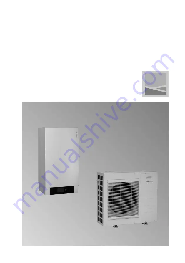
Vitocal 200-S
Type AWB 201.A04 to A13
Air/water heat pump, split version for heating operation
Type AWB-AC 201.A04 to A13
Air/water heat pump, split version for heating and cooling opera-
tion
For applicability, see the last page
VITOCAL 200-S
5601 429 GB
3/2011
Please keep safe.


