background image

Ver.17-01 


Original Operating Manual 


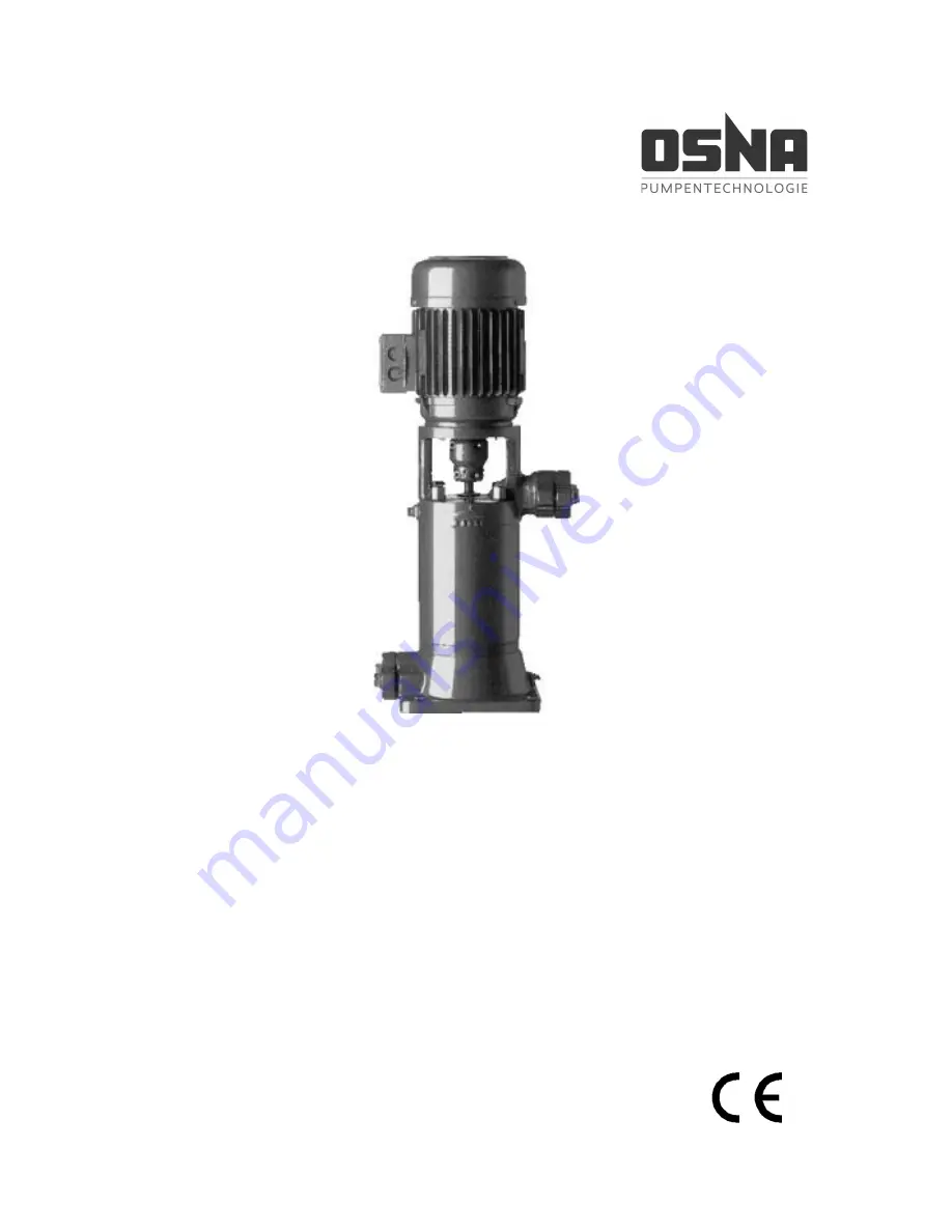
CVP High-Pressure Centrifugal Pump 


OSNA-Pumpen GmbH 

Brückenstrasse 3 

49090 Osnabrück, Germany 

Phone:  +49 541 1211 - 0 

Fax:   

+49 541 1211 - 220 

Internet: http://www.osna.de 

E-mail:  [email protected] 

Summary of Contents for CVP 423

Page 1: ... 01 Original Operating Manual CVP High Pressure Centrifugal Pump OSNA Pumpen GmbH Brückenstrasse 3 49090 Osnabrück Germany Phone 49 541 1211 0 Fax 49 541 1211 220 Internet http www osna de E mail info osna de ...

Page 2: ......

Page 3: ...thorized modes of operation 9 2 6 Special hazards 9 2 6 1 Explosion area 9 2 6 2 Hazardous pumping media 9 2 6 3 Noise emissions 9 3 LAYOUT AND FUNCTION 10 3 1 Labeling 10 3 2 Scope of delivery for a type CVP high pressure centrifugal pump 10 3 3 General information 11 3 4 Technical data 11 4 TRANSPORT AND INTERMEDIATE STORAGE 13 4 1 Transport 13 4 1 1 Unpacking and checking the delivery condition...

Page 4: ...1 4 Starting the pump 23 6 2 Decommissioning 24 6 2 1 Draining the pump and protecting against frost 25 6 3 Recommissioning 25 6 4 Mechanical seal 25 7 MAINTENANCE AND REPAIR 27 7 1 General information 27 7 2 Sending the pump to the manufacturer 28 8 FAULTS AND TROUBLESHOOTING 29 9 APPENDIX 32 9 1 Service spare parts accessories 32 9 2 Individual parts of the CVP centrifugal pump 33 9 3 Declaratio...

Page 5: ... the behavior 24 Table 10 Measures following longer shut down times 25 Table 11 Measures for return 28 Table 12 Fault number allocation 29 Table 13 Troubleshooting table 31 Table 14 Parts list of the CVP centrifugal pump 34 List of Images Figure 1 CVP model code 10 Figure 2 Scope of delivery for type CVP 10 Figure 3 Dimensions on the CVP centrifugal pump 11 Figure 4 Lifting a CVP centrifugal pump ...

Page 6: ...rrupted operation The operating specification does not take local safety regulations into account The owner bears full responsibility for compliance with these including on the part of the assembly personnel used This operating manual is part of the pump is valid for all type series mentioned describes safe and proper use in all phases of operation 1 2 Target groups Target group Task System owner ...

Page 7: ...ultiple steps Condition Reference Information note Table 4 Symbols and their meanings 1 5 Copyright changes The intellectual property and all copyrights re lated to this technical documentation remain exclusively with OSNA Pumpen GmbH All rights reserved in particular the right to repro duction and distribution of this documentation including translations thereof No part of this documentation may ...

Page 8: ...r The temperature of the pumping me dium must not exceed 80 C Avoiding obvious misuse examples Observe the operating limits of the pump for temperature pressure flow rate and speed The main areas of use are Pressure boosting systems heating systems hot and cooling water circula tion water supply systems power sta tions filtering systems fire extinguish er and sprinkler systems and pro cessing mach...

Page 9: ...n to this documentation en sure compliance with the statutory or other regulations for safety and acci dent prevention as well as the rele vant standards and specifications of the respective country Do not remove any technical stickers 2 2 2 Duties of the system owner Safety conscious work Observe the safety specifications detailed in this operating manual along with the occupa tional safety regul...

Page 10: ...g train ing to perform work on the pump under the supervision of specialist technical personnel Safety mechanisms Provide the following safety mecha nisms and ensure that they function correctly for moving components contact protection for the pump installed by the customer for potential electrostatic charges provide appropriate earthing Guarantee Please consult the manufacturer be fore carrying o...

Page 11: ...y the manufacturer help en sure safety The manufacturer bears no liability for the consequences of the use of other parts 2 5 Unauthorized modes of opera tion The operational safety of the machine is only guaranteed when it is used for the intended purpose according to the operating manual 2 1 Correct and proper use pg 6 Never exceed the limit values indicated in the technical data 3 4 Technical d...

Page 12: ...tate i e delivery without motor The motor is installed by the customer in a fully assembled state i e the pump is fitted with motor ex works Figure 2 Scope of delivery for type CVP 1 Pump 2 Drive motor 3 Coupling guard 4 Delivery side counter flange 5 Suction side counter flange oval The scope of delivery corresponds to the scope indicated in the order Please check that the delivery is complete up...

Page 13: ...ar plates are made from plastic the suction and delivery casings are made from gray cast iron and the stage casing is made from steel stainless steel available Other materials are also used depending on customer requirements or the needs of the pumping medium Only drive CVP pumps with electric motors that have a fixed bearing that cannot be shifted from the B side to the A side The complete unit i...

Page 14: ...59 55 50 44 37 28 17 8 394 90 2 2 793 525 426 8 87 86 84 82 78 73 67 59 49 37 23 10 470 100 3 0 916 611 426 10 108 107 105 102 98 91 83 73 61 46 29 12 546 112 4 0 1006 687 426 12 130 128 126 122 117 110 100 88 73 56 35 14 622 112 4 0 1082 763 426 14 151 149 147 143 137 128 116 102 86 65 40 16 698 132 5 5 1221 859 426 16 173 171 168 163 156 146 133 117 98 74 46 18 774 132 5 5 1297 935 426 18 195 19...

Page 15: ... receipt 2 Unpack the pump unit upon delivery and check for transport damage 3 Notify the delivery company of any transport damage immediately 4 Dispose of the packaging material in line with the applicable local regula tions 4 1 2 Lifting DANGER Risk of death or crushed limbs from falling transported goods Choose lifting equipment that is suitable for the total weight to be transported Do not sta...

Page 16: ...plastic covers 2 Ensure that the storage area meets the following conditions dry free of frost free of vibrations 3 Rotate the shaft once per month by several rotations NOTICE Damage to bearings due to high water pressure or splashing water Do not use water jets or steam jet cleaners to clean the bearing areas and motor NOTICE Damage to seals due to incorrect cleaning agent Ensure that the cleanin...

Page 17: ...icient WARNING Risk of poisoning and environmental dam age from pumping medium Use personal protective equipment when performing work on the pump Before disposing of the pump Collect any remaining pumping medium in the pump and dispose of it in line with the locally valid regulations Neutralize any pumping medium residues in the pump Dispose of the pump in line with the appli cable local regulatio...

Page 18: ... as well as for maintenance and repair work in particular for in stalling removing the pump and motor no effects from external vibrations on the pump bearing damage protection against frost 5 1 2 Preparing the base surface and foundations Ensure that the base surface and founda tions meet the following conditions level clean no oils dust or other contami nations foundations can support the weight ...

Page 19: ...mp in such a way that pre vents flooding of building sections as the result of a leak or when performing mainte nance work 5 2 2 Assembling the motor Clean the motor shaft of any anti rust agent and remove the keys if present Remove the socket head cap screws 29 and 30 of the coupling shells 28 place the motor on the delivery casing 20 or 26 and secure with screws see Table 14 pg 34 Manually tight...

Page 20: ...e the pump without the cou pling guard DANGER Risk of death due to rotating parts Use personal protective equipment when performing work on the pump Prevent the keys from being slung away when checking the direction of rotation Ensure sufficient clearance to rotating parts 5 2 3 Electrical connection CAUTION Electrical connection must be carried out by a specialist electrician in line with the spe...

Page 21: ...drill a screwdriver and a hexagonal socket wrench 1 Press the pump rotor down together with the coupling shells until the impel lers are in axial contact with the wear plate Mark the pump shaft 2 Raise the pump rotor with the coupling shells by the y dimension à Figure 7 pg 19 and mark the pump shaft 3 Evenly tighten the socket head cap screws 29 and 30 à Figure 6 pg 18 and Figure 7 pg 19 4 Check ...

Page 22: ...etermine the cost effective nominal width on a case by case basis Taper pieces to larger nominal widths should have an extending angle of approx 8 to pre vent increased pressure losses Install check valves and shut off devices depending on the type of system and pump à Figure 8 pg 20 Take appropriate measures to compensate any expansions of the pipelines caused by temperature influences in order t...

Page 23: ... medium Inlet sieve or strainer à Figure 8 pg 20 11 An inlet sieve or strainer protects the pump against large grain contaminations Monitoring fitting à Figure 8 pg 20 6 Monitoring fittings are required to monitor the suction and inlet pressure Monitoring valves help monitor the operating data Shut off valve à Figure 8 pg 20 5 A shut off valve is used to block the pipe dur ing assembly The shut of...

Page 24: ...due to hazard ous pumping media Collect any escaping pumping medium safely and dispose of in an environmentally friendly way NOTICE Material damage due to dry running Ensure that the pump is properly filled 6 1 3 Checking direction of rotation CAUTION Incorrect direction of rotation on the pump can lead to damage to the mechanical seal and a reduction in performance The pump shaft must rotate cloc...

Page 25: ...s are reinstalled and reactivated DANGER Never operate the pump without the cou pling guard 6 1 4 Starting the pump Pump correctly installed and connect ed Motor correctly installed and connect ed All connections established sealed and free of tension All safety mechanisms installed and function tested Pump correctly prepared filled and vented DANGER Risk of injury due to running pump Do not touch...

Page 26: ...gs Disassembled Deactivate motor and secure against unauthorized reactivation Put into stor age Observe storage measures 4 3 Storage pg 14 Table 8 Measures in the event of operational interruption Flow medium behavior Duration of operating inter ruption depending on pro cess short long Solid compo nents settle Flush pump Flush pump Solidified frozen non corrosive Heat or drain pump and contain ers...

Page 27: ...mmis sioning flush it thoroughly before recommis sioning Perform all further work steps in line with 6 1 Commissioning pg 22 Take the following measures before recom missioning following operating interruptions of 1 year Shut down time Measure 1 year Check visually for leaks 2 years Replace elastomer seals gaskets round seals shaft seal rings and gland packings Replace anti friction bearings Table...

Page 28: ...7 Commissioning decommissioning 26 CVP High Pressure Centrifugal Pump NOTICE Material damage due to dry running Ensure that the pump is properly filled ...

Page 29: ...leakage losses in vapor form It re quires no maintenance The reserve pumps must be activated once per week in order to ensure operational readi ness To do so switch the reserve pumps on and immediately off again Monitor the function of the additional connections The pump shaft is supported in the suction casing in a zero maintenance bearing shell made from PTFE graphite The pump shaft and motor sh...

Page 30: ...nents to the manufacturer together with a verifiable and completely filled out clearance certificate Request a clearance certificate from the manu facturer if required 2 Using the following table take the ac tion required for returning the pump according to the necessary repair Repair Action for return At customer Return defective compo nent to manufacturer At manufacturer Flush pump Send complete...

Page 31: ...en fitting X X Inlet suction pipe not completely opened Open fitting X X X X Inlet suction pipe pump or suction strainer blocked or encrusted Clean inlet suction pipe pump or suction strainer X X X Cross section of the inlet suction pipe too tight Enlarge cross section Clean suction pipe of encrustations Fully open fitting X Transport sealing cap not re moved Remove transport sealing cap Disassemb...

Page 32: ...sure side fitting Machine down impeller Consult manufacturer and adjust impeller diam eter X X X Geodetic delivery head pipeline resistance and or other resistanc es lower than designed Throttle flow rate with pressure side fitting Observe minimum flow rate here Machine down impeller Consult manufacturer and adjust impeller diam eter X X Viscosity lower than indicated Machine down impeller Consult...

Page 33: ...ned correctly Tighten tie bolts X Mechanical seal worn Replace mechanical seal X Defective casing seal Replace casing seal X Shaft sleeve penetrated Replace shaft sleeve and round seal X X X X Pump under tension Check pipeline connections and pump fastening Check coupling alignment Check support foot fastening X X Coupling incorrectly aligned Align coupling X X X X Motor runs on 2 phases Check fus...

Page 34: ...ist service providers Please provide a precise description of the fault so that our service technician can prepare and bring the required spare parts You can reach our customer service via the address on the last page Spare parts can be ordered via specialist re tailers Please refer to the type plate for the type designation In the event of any guarantee claims please provide the machine number on...

Page 35: ...9 Appendix CVP High Pressure Centrifugal Pump 33 9 2 Individual parts of the CVP centrifugal pump Figure 9 Explosion diagram of the CVP centrifugal pump ...

Page 36: ...ear plate 12 Impeller 13 Diffuser 14 Impeller top 15 Grub screw 16 Tie bolt 17 Cap nut 18 Screw lock 19 Stage casing 20 Delivery casing 21 Flange 22 Gasket 23 Hexagon head bolt with nut 24 Mechanical seal 25 Thrower 26 Delivery casing 27 Flange 28 Muff coupling split 29 Socket head cap screw 30 Socket head cap screw 31 Grub screw 32 Locking sleeve 33 Coupling guard 34 Socket head cap screw Table 1...

Page 37: ...linie 2014 35 EU EMV Richtlinie 2014 30 EU Ökodesignrichtlinie 2009 125 EG This declaration shall cease to be valid in the event of any modifications to the machine and or its pro tective mechanisms not agreed with us and approved in writing Applied harmonized standards and their references in the Official Journal of the European Union DIN EN 809 2012 DIN EN ISO 12100 2011 DIN EN ISO 13732 2008 DI...

Page 38: ...device Type _______________________________________________________________ Serial no _______________________________________________________________ is free of substances that are hazardous to health No special safety measures are required for further handling The device was fully drained and thoroughly cleaned inside and outside before dispatch Company institute _________________________________...

Page 39: ...______________________________________________ _________________________________________________________________________________ _________________________________________________________________________________ _________________________________________________________________________________ _________________________________________________________________________________ _________________________...

Page 40: ...ution you need Brückenstrasse 3 49090 Osnabrück Germany Consulting Training Phone 49 541 1211 0 Planning Maintenance Fax 49 541 1211 220 Project management Repair Internet http www osna de Assembly E mail info osna de OSNA customer service Tel 49 541 1211 254 Emergency service Tel 49 171 4151 674 ...

Reviews: