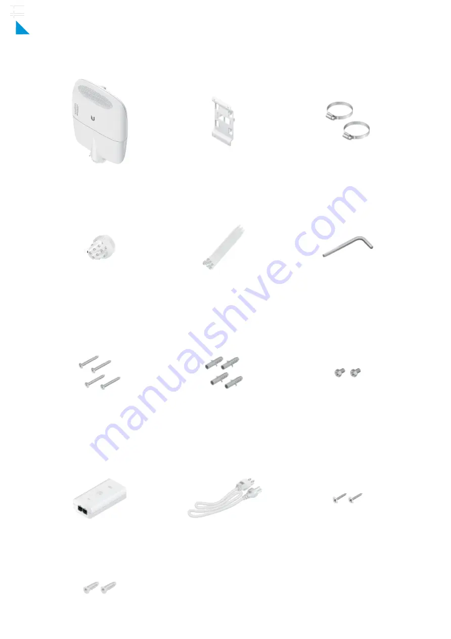
background image

EdgePoint Router

Wall-Mount Bracket

Metal Straps (Qty. 2)

Cable Sleeve

Cable Ties (Qty. 20)

S2 Hex Wrench

Wall-Mount Screws (Qty. 4)

Wall-Mount Anchors (Qty. 4)

Phillips Bolts (Qty. 2)

Gigabit PoE (54V, 1.5A) with

Mounting Bracket

Power Cord

PoE Screws (Qty. 2)

Package Contents

EP-R8 Quick Start Guide

×

Click for

Table of Contents

Summary of Contents for EdgePoint EP-R8

Page 1: ... Cable Sleeve Cable Ties Qty 20 S2 Hex Wrench Wall Mount Screws Qty 4 Wall Mount Anchors Qty 4 Phillips Bolts Qty 2 Gigabit PoE 54V 1 5A with Mounting Bracket Power Cord PoE Screws Qty 2 Package Contents EP R8 Quick Start Guide Click for Table of Contents ...

Page 2: ...Both PoE inputs can be used at the same time If there is a voltage difference the higher voltage source will be used rst The voltage from the initial source will drop as the load increases When the voltage drops to the same level as the lower voltage source then the lower voltage source will also start providing power Power Input Options 54VDC 6A 54V 1 5A on eth0 PoE In 54V 1 5A on PoE In Power Out...

Page 3: ...4V 1 5A PoE input from a secondary PoE adapter not included to power the EdgePoint and passive PoE output RJ45 port supports a 10 100 1000 Ethernet connection and accepts data and 54V 1 5A PoE input from the included Gigabit PoE Adapter to power the EdgePoint and passive PoE output RJ45 ports support 10 100 1000 Ethernet connections and passive 54 24V 4 pair PoE output for airFiber devices RJ45 po...

Page 4: ...ged into the SFP 1 port then the SFP port is active and the RJ45 port eth6 is deactivated If an SFP module is plugged into the SFP 2 port then the SFP port is active and the RJ45 port eth7 is deactivated Note For installations with extreme temperatures please use industrial grade ber SFP modules EP R8 Quick Start Guide Click for Table of Contents ...

Page 5: ...tivity LED SFP 1 2 Ports Off No Link Amber 10 100 Mbps Link Flashing Indicates Activity Green 1000 Mbps 1 Gbps Link Flashing Indicates Activity Green EdgePoint Powered On Off No PoE Amber 54V 4 Pair Passive Green 24V 4 Pair Passive Off No PoE Green 24V 2 Pair Passive Off No Link EP R8 Quick Start Guide Click for Table of Contents ...

Page 6: ...unting an optional PicoStationM2HP not included to the back of the EdgePoint You can use the PicoStationM2HP for wireless management of the EdgePoint Used to secure a ground wire not included Attaching the Cable Sleeve Note You have two options for using a 2 0 inch NPT National Pipe Thread male conduit not included Use the conduit instead of the Cable Sleeve Use the conduit to extend the Cable Sle...

Page 7: ... Wall Mounting Pole Mounting 1 2 3 Proceed to Grounding the EdgePoint EP R8 Quick Start Guide Click for Table of Contents ...

Page 8: ...Wall Mounting Note The Wall Mount Bracket must be anchored directly to a stud or other structurally stable surface 1 2 3 EP R8 Quick Start Guide Click for Table of Contents ...

Page 9: ...Grounding the EdgePoint 1 2 EP R8 Quick Start Guide Click for Table of Contents ...

Page 10: ...Connecting Ethernet 1 EP R8 Quick Start Guide Click for Table of Contents ...

Page 11: ...2 Note PoE is disabled by default 3 EP R8 Quick Start Guide Click for Table of Contents ...

Page 12: ...ecting SFP For information about compatible ber SFP modules visit ubnt link SFP_DAC_Compatibility 1 Note The corresponding RJ45 port will be deactivated 2 EP R8 Quick Start Guide Click for Table of Contents ...

Page 13: ...3 4 EP R8 Quick Start Guide Click for Table of Contents ...

Page 14: ...g Power Proceed to the appropriate section Connecting to the VDC Input Connecting Power Using PoE WARNING 48V is NOT supported Connecting to the VDC Input 1 2 EP R8 Quick Start Guide Click for Table of Contents ...

Page 15: ...Connecting Power Using PoE The following instructions show the PoE In eth0 port however you can use the PoE In port above eth0 instead 1 2 EP R8 Quick Start Guide Click for Table of Contents ...

Page 16: ...Optional 3 Accessing the EdgeOS Con guration Interface EP R8 Quick Start Guide Click for Table of Contents ...

Page 17: ...n check the DHCP server to see which IP address was assigned 1 Connect an Ethernet cable from eth1 on the EdgePoint to a LAN segment that has an existing DHCP server 2 Launch your web browser Enter the appropriate IP address in the address eld Press enter PC or return Mac 3 Enter ubnt in the Username and Password elds Read the Ubiquiti License Agreement and check the box next to I agree to the ter...

Page 18: ...tem with a static IP address on the 192 168 1 x subnet 3 Launch your web browser Type https 192 168 1 1 in the address eld and press enter PC or return Mac 4 Enter ubnt in the Username and Password elds Read the Ubiquiti License Agreement and check the box next to I agree to the terms of this License Agreement to accept it Click Login The EdgeOS Con guration Interface will appear allowing you to c...

Page 19: ...ected device supports PoE and the supplied voltage 1 Go to Actions PoE for the interface you want to con gure 2 Con gure the PoE setting For eth1 eth2 select Off 24V 4pair or 54V 4pair For eth3 eth7 select Off or 24V Then click Save WARNING Do NOT connect 4 pair PoE devices such as airFiber devices to ports eth3 eth7 They support 2 pair PoE only Note If the PoE screen states that PoE is not supporte...

Page 20: ... 4 5 3 6 7 8 Passive PoE eth0 and PoE In PoE In DC Only Passive PoE Output 2 54V or 24V 1 4A 4 Pair 1 2 4 5 3 6 7 8 Passive PoE eth1 to eth2 5 24V 0 7A 2 Pair 4 5 7 8 Passive PoE eth3 to eth7 Power Monitoring 1 DC Terminal Block Input Power 2 RJ45 PoE In and eth0 Input Power Supported Voltage Range 42 to 56VDC 48V is NOT Supported Button Reset LEDs System Power eth0 Speed Link Activity eth1 to eth...

Page 21: ...ne that is not the provided approved type Never use an adapter plug to connect to a 2 wire outlet as this will defeat the continuity of the grounding wire b The equipment requires the use of the ground wire as a part of the safety certi cation modi cation or misuse can provide a shock hazard that can result in serious injury or death c Contact a quali ed electrician or the manufacturer if there ar...

Page 22: ...tion manual may cause harmful interference to radio communications Operations of this equipment in a residential area is likely to cause harmful interference in which case the user will be required to correct the interference at his own expense ISED Canada CAN ICES 3 A NMB 3 A Australia and New Zealand Warning This equipment is compliant with Class A of CISPR 32 In a residential environment this e...

Reviews: