background image


Tycon Systems 


14641 S 800 W  

  Bluffdale UT 84065  



 tyconsystems.com                 Page 1


EZ

-

Bridge ®

-

 LT2 Series   Initial Set

-

Up Procedure and Checklist


Thank you for choosing the EZ

-

Bridge®  Wireless Antenna System.


Each Antenna system is factory tested and pre

-

configured so that most applications 


are truly  

Plug and Play


Some package models will require additional user

-

provided Ethernet Cat5/6 jumper cables to 


complete the necessary connections between each Antenna, each PoE Injector and your 


Network Devices.


                                   O      Unbox all system components within the same room on a  non

-

conductive table or floor.


                                   O       Identify and keep separate Antenna 

A

” 

and Antenna 

B

” 

as each will be initialized separately.


                                                     (The PoE  wall pack  injectors are identical and may be used with either antenna)


                                         Step One:   Begin  set

-

up procedure for Antenna 

A


With the PoE wall

-

pack injector 

unplugged

 from AC power —


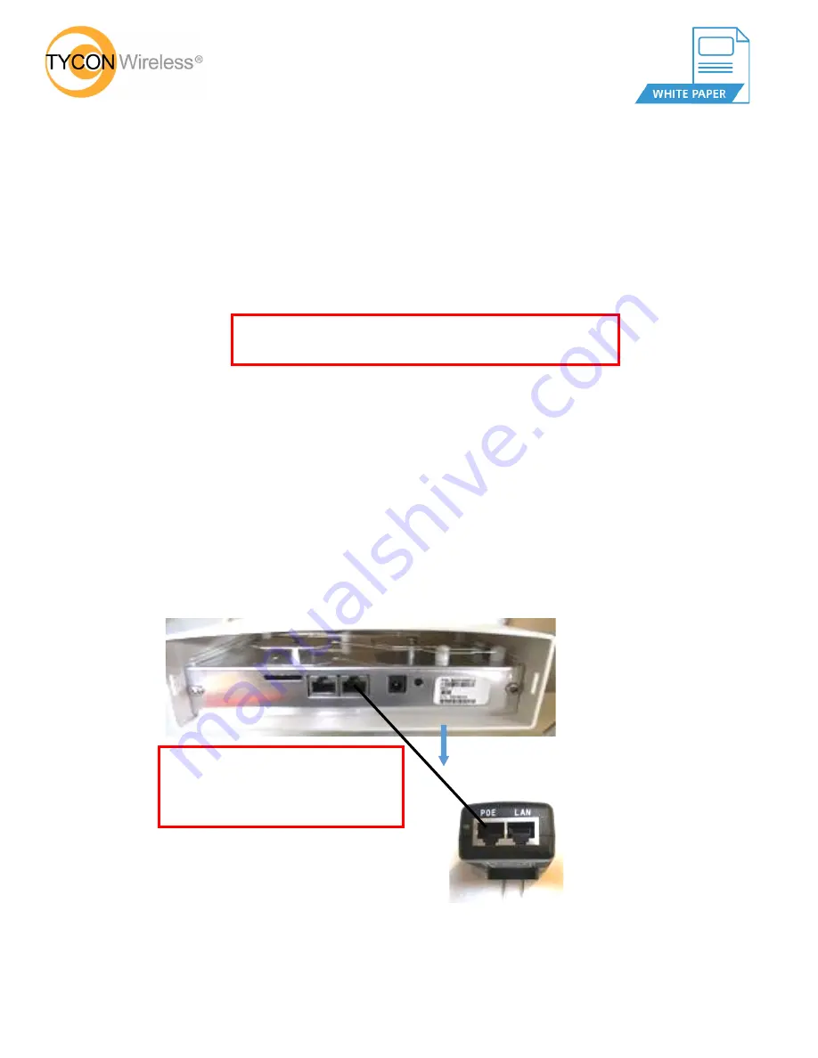
                                        O     Remove the bottom cover from the antenna housing to access the connection points.


                                        O      Insert one end of a CAT5/6 jumper cable into the center RJ45 port.  

(Center Port aligns with the cover)


                                                  and the other end into the 

PoE

” 

port of the injector as shown.


IMPORTANT! Before installing any devices, please read all of 
the cautions and warnings contained in the system manual.


Warning! These antennas utilize (12 –

24 

VDC)


Do not connect to Standard PoE Power Sources.


Higher voltages  will damage units and void


the warranty


                     O     

With another CAT5/6 jumper cable, insert one end into the 

LAN

” 

port of the


                           Injector and the other end into a spare data port of your Switch or Router that is


                           Connected to an Internet  source as shown at the top of page 2.


Cat 5/6


Jumper


7 August 2019


Summary of Contents for Wireless EZ-Bridge LT2 Series

Page 1: ...identical and may be used with either antenna Step One Begin set up procedure for Antenna A With the PoE wall pack injector unplugged from AC power O Remove the bottom cover from the antenna housing to access the connection points O Insert one end of a CAT5 6 jumper cable into the center RJ45 port Center Port aligns with the cover and the other end into the PoE port of the injector as shown IMPORT...

Page 2: ...er Green Power On LED Step Two Antenna B Initialization With the PoE wall pack Injector unplugged from the wall outlet O Remove the bottom cover to access the connection points O Insert one end of a CAT5 6 jumper cable into the center port of the antenna and the other end into the PoE port of the injector as shown below CAT5 6 Jumper O Plug the Injector into a constant 110 VAC wall outlet The Ante...

Page 3: ...ge the Antennas within the same room so there is at least an 8 foot separation as shown below 8 ft Separation Antenna A Antenna B Router or Switch Internet Source PC O From the B Side PC try to access a known web site via the Internet O If able to access the Internet then the Antenna System is functioning properly O Go to page 4 and follow the shut down procedure O If unable to access the Internet...

Page 4: ...ment in their final destinations O Go to each wall pack PoE injector and unplug from the wall outlet O You may now disengage the CAT5 6 jumper cables O You are now ready to install the Antennae and cabling Be sure to observe all of the warnings and safety precautions in the User Manual O Go to the installation section of the User Manual and follow the steps for mounting the Antennae ...

Reviews: