


Tri-M Technologies Inc.
Toll Free: 1.800.665.5600
Direct: +1.604.945.9565
Email: [email protected]
Web: www.tri-m.com
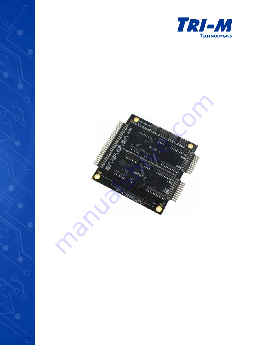
TCB1000 Series
User Guide
CAN Bus, Socket Modems & Serial Communication
The Tri-M Systems TCB1000 Series User Manual is an essential guide for users looking to maximize the potential of their TCB1000 device. This comprehensive manual is available for free download from manualshive.com, providing step-by-step instructions and troubleshooting tips to improve your experience with this exceptional product.
Tri-M Technologies Inc.
Toll Free: 1.800.665.5600
Direct: +1.604.945.9565
Email: [email protected]
Web: www.tri-m.com
TCB1000 Series
User Guide
CAN Bus, Socket Modems & Serial Communication


