background image


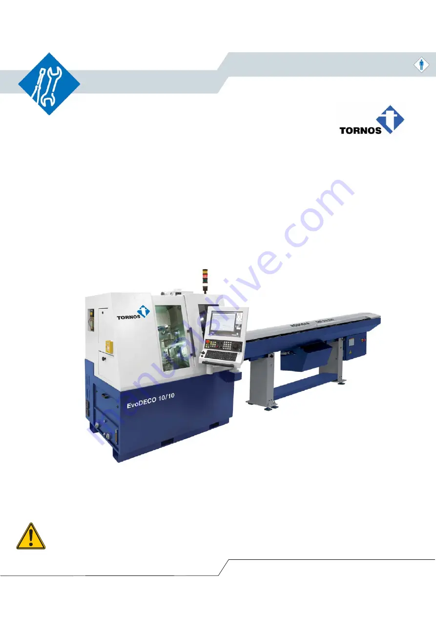
EvoDECO 10/10 & 10/8

INSTRUCTION MANUAL

ENGLISH VERSION TRANSLATED FROM THE ORIGINAL VERSION

TORNOS SA CH-2740 MOUTIER

http://www.tornos.ch

Ref.

: 298061_fr

 – Print

e

d in S

w

itz

e

rland

 - 

Co

py

right

 © 19

99-

201

2

Attention!

Read this precautions before, 
all users must read the instruction manual and pay 
particular attention to the "SAFETY INSTRUCTIONS" !
Keep this document for future reference.

Summary of Contents for EvoDECO 10/10

Page 1: ...ERSION TORNOS SA CH 2740 MOUTIER http www tornos ch Ref 298061_fr Printed in Switzerland Copyright 1999 2012 Attention Read this precautions before all users must read the instruction manual and pay particular attention to the SAFETY INSTRUCTIONS Keep this document for future reference ...

Page 2: ......

Page 3: ...struction Manual EvoDECO 10 10 10 8 298061_en 07 12 I Identification I 1 Document Instruction Manual EvoDECO 10 10 10 8 No 298061_en Version manager Version Date Description 06 12 01 06 2012 First edition ...

Page 4: ...struction Manual EvoDECO 10 10 10 8 I 2 Manufacturer TORNOS SA Rue Industrielle 111 CH 2740 MOUTIER SWITZERLAND Tel 41 0 32 494 44 44 Fax 41 0 32 494 49 03 contact tornos ch www tornos ch I 3 Products EvoDECO 10 10 10 8 ...

Page 5: ...3 Give first aid 4 Inform ambulance staff Position s of first aid box Fire 1 Notify the fire brigade 2 Find shelter for yourself and others 3 Close window s and door s 4 Inform the fire brigade staff 5 Put the fire out Evacuation 1 Notify the people in danger and evacuate them 2 Leave the premises using the stairs 3 Go to the assembly point Assembly point s Person in charge of keeping the emergenc...

Page 6: ...298061_en 07 12 Instruction Manual EvoDECO 10 10 10 8 ...

Page 7: ...1 Electrical connection 1 10 1 5 2 Pneumatic connection 1 10 1 6 Guard opening closing 1 11 1 7 Machine connection to the barfeeder 1 12 1 7 1 Description 1 12 1 7 2 Necessary specifications 1 12 1 7 3 Capacity and length of the remnant 1 14 1 7 4 Length of the remnant and part for SBF 216 1 14 2 Installation 2 1 2 1 Work environment specific to the installation 2 2 2 1 1 Order and cleanliness 2 2...

Page 8: ... power sources 2 13 2 9 1 1 Electrical power supply 2 13 2 9 1 2 Pneumatic supply 2 14 2 9 2 Emptying liquids 2 14 2 9 2 1 Cutting liquid 2 14 2 9 2 2 Spindle coolant 2 14 2 9 2 3 Greasing liquid 2 14 2 9 2 4 Machine cleaning 2 14 2 10 Moving the machine 2 15 2 10 1 Machine maintenance 2 15 2 10 2 Lifting the machine 2 16 ...

Page 9: ...ne see the document Transportation sheet 1 1 Machine identification The warning plate contains the following information Fig 1 Location of parts Marker lines Function 1 Machine type 2 Serial number 3 Machine identification number 4 Year of manufacture Mandatory The serial number must be quoted for all contacts with TORNOS SA departments 1 2 3 4 ...

Page 10: ... 2 1 Dimension specifications 1 2 1 1 Dimensions EvoDECO 10 10 10 8 Fig 2 Name Unit Value Dimensions Length m 1 870 Width m 1 140 Width NC control expanded m 2 045 Height without signal lamp m 1 950 Height doors and guards open without signal lamp m 2 350 Spindle height m 1 100 Weight Complete machine kg 1650 ...

Page 11: ...Instruction Manual EvoDECO 10 10 10 8 1 Installation conditions 298061_en 07 12 1 3 1 2 1 2 Dimensions EvoDECO 10 10 10 8 with bar feeder SBF 216 EVO Fig 3 ...

Page 12: ...or access all around the machine and the bar feeder This clearance space is reserved and authorised only to those people working on the machine for production or maintenance purposes Specifications Name Unit Value Minimum safety clearance all around the machine m 1 Warning The clearance space of 1 metre around the machine must consider the length of the chip tank which is 1 3 metres ...

Page 13: ...n Scrapping Scrapping the machine its components and the elements connected to it must be performed in observance of the environmental regulations in force in the country of installation Special attention must be paid to lubricant oils batteries electronic parts which must be handed over to a recycling plant Regulations in force The user should find out more from the relevant authority in the coun...

Page 14: ... disposition de son personnel des informations utiles sur le bruit ainsi que des protecteurs d ouïe au poste de travail et leur port est recommandé Specifications Name Unit Value Maximum ambient humidity 79 Ambient temperature of the workplace C 5 35 Relative temperature C 15 Note The parameters which influence the real exposure levels include the duration of the operator s exposure to noise the s...

Page 15: ...e 10m3 per kilogram of CO2 in order to allow use of the fire fighting equipment reference 5483 Warning If the room volume is too small there is a risk of death from asphyxiation when using the fire fighting equipment Minimum shop volume per machine Name Unit Value EvoDECO 10 10 10 8 DCS PTO m3 100 Information The premises where the machine is installed must be adequately ventilated Mandatory Obser...

Page 16: ...may be significant It is highly recommended in all cases to install a fume and oil spray extraction system All TORNOS SA machines are equipped with a connection for a fume and vapour extractor or collector Warning Despite installation of the fume discharger the treatment system may be insufficient during heavy release of fumes Mandatory During installation of a fume or vapour collector or extracto...

Page 17: ...re fighting device centralised suction check valve or suction motor brake fitted on the machine controlled by the emergency stop or fire fighting system this is under the responsibility of and at the expense of the buyer Danger Make sure the motor rotates in the right direction Check the rotating field Attention Make sure the device is at a complete standstill and disconnected from the electricity...

Page 18: ... Mandatory The machine must be supplied with dry air and without oil If the air of your network contains oil or condensate it is necessary to install an air dryer at the circuit inlet to avoid malfunctioning or breakdowns of the machine Quality according to ISO 8573 1 Name Unit Value Operating pressure bar 6 Average consumption of 6 bar system max m3 h 20 Flow rate l min 100 Quality class shop sta...

Page 19: ...qualified person is authorised to work inside the electrical cabinets or on electrical parts Description of parts Rep Function Operator access Maintenance access 1 Mechanical part lateral access guard lock X X 2 Chip tank access guard lock X X 3 Electrical cabinet rear guard lock X 4 Mechanical part rear access guard lock X 1 2 4 3 ...

Page 20: ... preparation of the bar should be necessary to cover the entire range of capacity For a barfeeder No preparation of the bar should be necessary for bars with a diameter of Ø 1 to Ø 10 mm and remnant extraction should be from the back When changing the bar it is necessary to be able to perform a calibration of it to position it a few mm outside the guidebush before the cut off in order to avoid hav...

Page 21: ...Instruction Manual EvoDECO 10 10 10 8 1 Installation conditions 298061_en 07 12 1 13 Fig 7 ...

Page 22: ... and part for SBF 216 Description of measurements in the previous figures Measurement Function C Ø collet d Ø guidebush L1 Length of collet clamping L1 Length of collet bush L2 Length of the collet push rod P Ø pushrod Length of the remnant and part based on the collets in guidebush mode Spindle collet Ø turning endpiece Ø guide bar Ø guide tube Ø max bar Minimum remnant length Maximum remnant len...

Page 23: ...Instruction Manual EvoDECO 10 10 10 8 2 Installation 298061_en 07 12 2 1 2 Installation ...

Page 24: ...e floor or on workstations Clean interior of the machine regularly Warning Order and cleanliness around the machine are key factors for safety danger of slipping falling and injury Mandatory The user in charge of the machine maintenance must be used to handling travelling cranes and hoists Warning When performing maintenance on the machine make sure nothing is in the way Information The premises w...

Page 25: ...Instruction Manual EvoDECO 10 10 10 8 2 Installation 298061_en 07 12 2 3 Fig 1 ...

Page 26: ...ve the wooden wedges and the cords outside the machine 2 Open the cover and remove the locking parts located in the interior Warning All installations must be performed by a TORNOS technician or an authorised specialist who has taken an installation training course held by TORNOS SA Starting condition Machine in place and stabilised Step Key Action Observation 1 Carefully clean all the parts coate...

Page 27: ...al connection For more information on the subject of electrical specifications see the chapter Description in the instruction manual For more information refer to the electric schematic diagrams in the electrical cabinet Information The machine can be connected directly to the local mains or through an autotransformer Warning If the sector supply is different than 400 V 50 Hz 20 A 10 kVA or 460 V ...

Page 28: ...isconnect the mains 2 Connect the mains 3 on the machine terminal board 2 Minimum cable cross section 6 mm See figure 2 below 3 Turn the local mains on Minimum cable cross section 6 mm See figure 2 below 4 Turn the main switch 1 ON 5 Check the connection to the local mains 380 420 V Europe 440 480 V US 6 Check the rotating field 7 Check the voltage at the socket 220 240 V Europe 100 110 V US 1 2 3...

Page 29: ...local mains electrical installation 4 This is to be carried out by a qualified and authorised member of staff 2 Connect the autotransformer mains cable 3 on the machine terminal block 1 Minimum cable cross section 6 mm See figure 3 below 3 Reconnect the autotransformer 5 to the local mains electrical installation 4 4 Turn the main switch 2 ON 5 Check the rotating field 6 Check the voltage at the s...

Page 30: ...breakdowns of the machine Name Unit Value Quality according to ISO 8573 1 Operating pressure bar 6 Average consumption of 6 bar system m h 20 Quality class shop standard 4 Maximum particle size µm 15 Mass concentration mg m 8 Maximum pressurised dew point C 3 Maximum concentration in oil mg m 5 Fast connection G 1 4 Starting condition Machine in place and stabilised Step Key Action Observation 1 C...

Page 31: ... the machine Fig 5 Starting condition Machine in place and stabilised Machine power off Step Key Action Observation 1 Remove the guard plate 1 Square key lock 2 Fill the tank 2 with glycerine Machine cable protection Warning When moving the machine the maximum rocking tolerance is 5 If the rocking exceeds the tolerance the tank of glycerine must be emptied ...

Page 32: ...ing liquid tank For more information on the subject of cutting liquid see the Logbook manual Fig 6 Starting condition Machine in place and stabilised Step Key Action Observation 1 Remove the guard plate 1 Square key lock 2 Fill the tank With VG15 cutting liquid up to the upper limit shown on the gauge 2 1 2 ...

Page 33: ...uid see the Logbook manual Fig 7 Starting condition Machine in place and stabilised Step Key Action Observation 1 Fill the tank 3 through the opening 5 With VG68 type grease up to the upper limit shown on the gauge 4 Capacity 1 7 l 2 Check the setting of the flow 1 Adjust with the button 2 Positions 1 to 5 for 1 to 5 cm hour Standard adjustment 2 cm hour 1 2 3 5 4 ...

Page 34: ...it reservoir For more information on the subject of coolant see the Logbook manual Fig 8 Starting condition Machine in place and stabilised Step Key Action Observation 1 Fill the tank 2 through the opening 1 With ISO VG2 type coolant liquid up to the upper limit shown on the gauge 3 Capacity 7 l 1 2 3 ...

Page 35: ...o another space For more information on unpacking the case see the Transportation Sheet 2 9 1 Disconnecting power sources 2 9 1 1 Electrical power supply Fig 9 Warning In order to avoid any personal injury or damage to the equipment please read the instructions in the Safety instructions manual Step Key Action Observation 1 Turn the main switch 1 to position 0 2 Disconnect the mains 3 Disconnect t...

Page 36: ... 1 Information The cut off liquid must be pumped using an external pump and stored in appropriate containers Information It is not necessary to drain the spindle coolant circuit to move the machine Information It is not necessary to drain the centralised greasing circuit to move the machine Danger This operation is to be done in a well ventilated area Warning Be careful not to damage or change any...

Page 37: ... covers closed Electrical and pneumatic supplies disconnected Step Key Action Observation Danger The mobile parts must be locked by transport clamps Danger All personnel should stay clear of the range of action during all machine handling operations Lift and move the machine with a pallet transporter or forklift As indicated in the drawings below 1 2 ...

Page 38: ...cked by transport clamps Danger All personnel should stay clear of the range of action during all machine handling operations 1 Place the lifting bars under the machine in the provided openings As indicated in the drawing below Min working load 1650 kg ø of the bars 50 mm 2 Position the straps Min working load 1650 kg Warning All personnel should stay clear of the range of action during all machin...

Reviews: