

MAX-2533
Mobile Rack / HDD Canister
with SAS & SATA Backplane
P/N: RC2300101A
*Hard Drive(s) not included
*Require Hot-Swap SAS or SATA Controller Card/Motherboard
©
2010 Thermaltake Technology Co., Ltd. All Rights Reserved. 2010.08
All other registered trademarks belong to their respective companies.
www.thermaltake.com
Hardware Installation
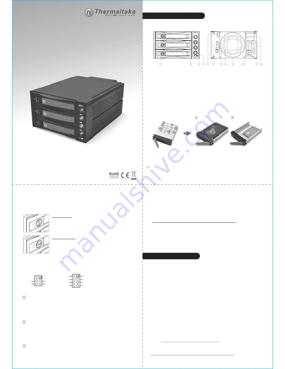
1. Front & Back Views
2. Hard Drive Disk Installation
3. LED Status & Switch Button Specifications
1 =
2 = Reset Switch for Buzzer Alarm &
Overheating LED
3 = Individual HDD Power Button &
Status LED
4 = Fan Sensor LED
HDD Tray Safety Lock & Eject Button
5 = IJP3: Extension Function Jumper
6 = IJP1: Temperature Setting Jumper
7 = J4: Fan RPM Adjustment Switch
8 = HDD Status LED On (O) & Off (X) Switch
9 = 80mm Cooling Fan
10 = SAS / SATA Data Connectors
11 = Buzzer Alarm / Speaker
12 = SATA & Molex Power Connectors
*
Hard Drive not included
1. Insert 2.5” or 3.5” Hard Drive into the HDD Tray
2. Use the provided screws and fasten them into highlighted 2.5” or 3.5” holes from the
bottom of the Tray into the bottom of the 2.5” or 3.5” Hard Drive
3. After the screw installation, slide the HDD Tray back to the HDD Canister Base.
4. Next, follow the Quick Installation in next page for the rest of the Setup.
Note:
- All New / Raw hard drive(s) should follow hard drive / system manufacturer guideline or
visit Thermaltake FAQ Site to partition, format and any necessary steps prior initial
usage. Hard drive(s) not properly partitioned or formatted will not work. ( See below for
General Guideline to Partition & Format “NEW & RAW” hard drives)
- RAID Compatibility & Configuration bases on RAID Controller Card / On-Board RAID
Controller Chipset.
- All New or Raw Hard Drive requires an initial Partition & Format after Hardware Setup.
1. Fasten all screws necessary for any needed hard drive(s).
2. Slide any needed hard drive tray(s) back into the HDD canister base.
3. Push the Red-Color handling bar into closed position.
4. To Lock the Safety Lock for each HDD Tray, Push & Hold HDD Tray Door Handle in
closed position while switching the Safety Lock.
5. Connect all necessary data and power cable onto the rear end of HDD canister base.
6. Connect all necessary data and power cable from the rear end of HDD canister base
to either the SAS/SATA Controller Card or SAS/SATA Connectors on the
motherboard.
7. Turn on the Power of your computer and wait until Operating System finish loading up.
8. Turn on all necessary HD1~HD3 Power Button(s) for each Hard Drive.
9. Wait for your operating system to automatically search and recognize your newly
installed hard drive(s) before usage.
10. For optional RAID Configuration & Setup, please follow the user manual instructions
from your SAS/SATA Controller Card or Motherboard.
11. All New or Raw Hard Drive requires an initial Partition & Format. For instructions on
how to partition & format, please visit Thermaltake FAQ
Site: http://www.thermaltakeusa.com/support/FAQ
Or, See below for
General Guideline to Partition & Format “NEW & RAW” hard drives
Quick Installation
1
3
2
Safety Lock Positions:
Jumper / Pin Assignments:
AJP1
AJP2
AJP3
65
℃
60℃
55
℃
**
Push & Hold the HDD Tray Handle in Closed Position while Switching the Safety Lock.
Fan RPM :
HIGH = 3,000 RPM
LOW = 2,300 RPM
FLEDR
FLED+
FLEDG
RESET
TLEDR
5V+
TLEDG
GND
2 RESET LED & Switch Button
When Overheating occurs (Default Setting = 60
℃
), the Buzzer alarms,
and the RESET LED
blinks in Red color. To deactivate the alarm, press the RESET LED &
Switch Button once, and the LED will go off at the same time.
3 HD1 ~ HD3 LED & Switch Button
HD1, HD2 and HD3 Buttons serve as Individual Power Switch Button and
Hard Drive Status Indicators.
LED displays in Blue Color when Power On by pressing the button once.
LED displays and blinks in Red Color when Hard Drive is being access.
4 Fan Sensor LED
LED displays in Blue Color when the Fan functions properly.
LED displays in Red Color when the Fan failed.
OPEN Position
1. PUSH to Eject HDD Tray Handle
2. Pull the Tray Handle to Slide out HDD Tray
LOCKED Position
The Safety Lock Safeguards the Hard Drive(s) in proper
position & Prevent any Ejection while HDD in operate
RESET
HD1
HD2
HD3
L
O
W
H
IG
H
POWER1
IJP3
IJP1
J4
H
D
1
H
D
2
H
D
3
P
O
W
E
R
2
1
2
3 4 5 6
7 8
9
10
11 12
= 3.5” HDD Screw Holes
= 2.5” HDD Screw Holes
藍色線條為尺寸標示,請勿印刷上去!
210 mm
297 mm
產品料號
RC23 00101A
MAX-2533
說明書
X
10
/0
9
/
14
A
產品名稱
印刷項目
子件料號
發稿日期
版本
105G
是
X
雙銅
單色
無
無
其他特殊處理效果
表面處理
2
厚度
(g/m )
折數
材質
雙面印刷
印刷色彩
單面印刷
規格樣式
單張
MARKETING
CHECK
DESIGN
PRODUCT GM
Peipei
刀模 線
折2次
十字對折


