INSTALLATION INSTRUCTIONS
32-F218 / SINGLE SIDED COMMUNICATING DEADBOLT
For use on doors 1-3/8” to 1-3/4” (35-45 mm) thick
Tools required for new installation:
• Phillips head screwdriver
• 2-1/8” (54 mm) hole saw
• 1” (25.4 mm) drill bit
• Chisel
Tools required for replacement installation:
• Phillips head screw driver
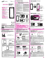
THUMB TURN
ASSEMBLY
MOUNTING
SCREWS
DEADBOLT
BLANK PLATE
STRIKE
WOOD FRAME
REINFORCER
DUST BOX
1
MARK DOOR
Measure center line of lock; height as
desired from finished floor. Select 2-3/4”
or optional 2-3/8” backset, fold and apply
template to interior side of door and mark
center of door as indicated on template.
Mark center hole on door face through
guide on template.
2
DRILL HOLES
Drill 2-1/8” (54 mm) hole through door face as
marked for lockset. (It is recommended that
holes be drilled from both sides on wood doors
to prevent splitting.) Drill 1” (25.4 mm) hole in
center of door edge for latch.
CENTER LINE
MARK FOR 2-1/8”
(54 mm) HOLE
ON DOOR FACE
MARK FOR
1” (25.4 mm)
HOLE IN
DOOR EDGE
2-1/8” (54 mm)
HOLE
1” (25.4 mm)
HOLE
3
INSTALL DEADBOLT
A. Insert latch in hole, keeping it parallel to face of door. Mark outline of latch face plate and remove latch.
B. Chisel 1/8” (3 mm) deep or until latch plate is flush with door edge.
C. Insert latch and tighten to the door using #8 screws.
DOOR EDGE DOOR SIDE
TEMPLATE
FOLD HERE
ON DOOR EDGE
Ø2-1/8” (54 mm) HOLE
2-3/8” (60 mm) BACKSET
2-3/4” (70 mm) BACKSET
Make 1” (25.4 mm) hole at center of door edge
45 mm
(1-3/4”)
40 mm
(1-9/16”)
35 mm
(1-3/8”)
A.
B.
C.
TEMP
LATE