SteelMax D3X RS, Operator'S Manual
Introducing the SteelMax D3X RS with advanced features and cutting-edge performance. Unlock the full potential of this exceptional tool with our comprehensive Operator's Manual, available for free download at manualshive.com. Get the most out of your D3X RS experience with just a few simple clicks.
Share
Download


Reviews:
No comments
Related manuals for D3X RS

GR195
Brand: Jata electro Pages: 20

SPJ-122Hi
Brand: HAKKEN Pages: 20

REXON 3.1
Brand: Landmann Pages: 68

KK-1501
Brand: MICRO CHEF GRILL Pages: 60

ABH 18 Series
Brand: Fein Pages: 61

42914
Brand: Omcan Pages: 12

L (21")
Brand: Kingstone Pages: 188

TYG 3608
Brand: Clatronic Pages: 62

"T" SERIES
Brand: Viking Pages: 30

120QP-21500 Series
Brand: Quackenbush Pages: 20

ASTERIA ESSENTIAL
Brand: Taurus Pages: 36

PRO22K-LEG-3
Brand: Napoleon Pages: 20

ASV 14 A
Brand: Narex Pages: 32
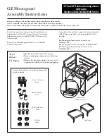
ZX48CTACSS
Brand: GE Pages: 4

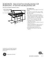
ZGG420LCPSS
Brand: GE Pages: 2

ZGG542LCPSS
Brand: GE Pages: 2
ZGG540LCPSS
Brand: GE Pages: 2

RK959
Brand: GE Pages: 23


