SpinCore Technologies RadioProcessor-G, Owner'S Manual
The SpinCore Technologies RadioProcessor-G is a powerful device designed for signal processing. Easily navigate its features with the comprehensive Owner's Manual available for free download on our website. Maximize the capabilities of your RadioProcessor-G with this essential manual. Download it now from manualshive.com.
Share
Download


Reviews:
No comments
Related manuals for RadioProcessor-G
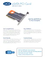
eSATA PCI Card
Brand: LaCie Pages: 2

8STPEX2S953LP
Brand: StarTech.com Pages: 2

HSB-811P
Brand: Aaeon Pages: 55

PB- 2500J-CSM
Brand: Neousys Technology Pages: 44

54546
Brand: Hama Pages: 24

U-3000
Brand: Avante Pages: 13

CR-02
Brand: ACME Pages: 28

sampo
Brand: Nordic ID Pages: 12

EXA51E
Brand: Nordic ID Pages: 35

IM700
Brand: PAX Pages: 10

GV-4008
Brand: GeoVision Pages: 4

MIFARE Classic AY 5B Series
Brand: Rosslare Pages: 2

AYC-Q6355
Brand: Rosslare Pages: 69

U2-CR-58N1
Brand: Kanguru Pages: 2

Micro CF
Brand: Kanguru Pages: 7

DS-33003
Brand: Digitus Pages: 5

DS-30201-5
Brand: Digitus Pages: 4

DS-30105
Brand: Digitus Pages: 5


