SpinCore Technologies PulseBlasterESR-PRO SP18A, Owner'S Manual
The SpinCore Technologies PulseBlasterESR-PRO SP18A is a versatile programming manual for advanced users. Download the free Owner's Manual from manualshive.com to explore in-depth programming capabilities and maximize the potential of this innovative product. Unlock new features and functionalities with the comprehensive manual at your fingertips.
Share
Download


Reviews:
No comments
Related manuals for PulseBlasterESR-PRO SP18A

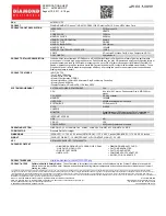
Gryphon GD4100
Brand: Datalogic Pages: 10

OBID classic-pro ID CPR.03.20-CD
Brand: Feig Electronic Pages: 40

25713
Brand: Vivanco Pages: 22
SKU 4670PE31GDT
Brand: Diamond Multimedia Pages: 1

802.11b/g Wireless Mini PCI Card WM2504
Brand: Abocom Pages: 2

GeForce RTX 2070 GAMING Z 8G
Brand: MSI Pages: 47

1524-331
Brand: DoorKing Pages: 3

N640GT series
Brand: MSI Pages: 1

GV-N57128DE
Brand: Gigabyte Pages: 39

TT-premium S-2300
Brand: TechnoTrend Pages: 4

Sound Blaster Pro
Brand: Creative Pages: 23

BCM94350ZAE
Brand: Broadcom Pages: 16

BCM943225HMB
Brand: Broadcom Pages: 20

OMNI 3300
Brand: E-Chex Pages: 2

GT 630 1024MB D5
Brand: Gainward Pages: 1

AXE4DL
Brand: ATCOM Pages: 18

UFG-10 series
Brand: Unigraf Pages: 11

HD Capture Box 1080p
Brand: ClearClick Pages: 10


