background image

3-874-289-

15

 (1)

© 2008 Sony Corporation

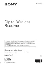
Digital Wireless
Receiver

Operating Instructions

Before operating the unit, please read this manual thoroughly 
and retain it for future reference.

DWR-S01D

F

The supplied CD-ROM includes the Operating Instructions for the DWR-S01D 
digital wireless receiver (English, French, German, Italian, Spanish, and 
Japanese versions) and the frequency lists (English and Japanese versions) 
in PDF format. 
For more details, see “Using the CD-ROM Manual” on page 9.

Summary of Contents for DWR-S01D

Page 1: ...thoroughly and retain it for future reference DWR S01D F The supplied CD ROM includes the Operating Instructions for the DWR S01D digital wireless receiver English French German Italian Spanish and Japanese versions and the frequency lists English and Japanese versions in PDF format For more details see Using the CD ROM Manual on page 9 ...

Page 2: ...ions about this product you may call Sony Customer Information Service Center 1 800 222 7669 or http www sony com For the customers in Canada This Class B digital apparatus complies with Canadian ICES 003 Operation is subject to the following two conditions 1 this device may not cause interference and 2 this device must accept any interference including interference that may cause undesired operat...

Page 3: ...o comply with the FCC RF exposure compliance requirements no change to the antenna or the device is permitted Any change to the antenna or the device could result in the device exceeding the RF exposure requirements and void user s authority to operate this device This device complies with FCC radiation exposure limits set forth for uncontrolled equipment and meets the FCC radio frequency RF Expos...

Page 4: ... met de essentiële eisen en de andere relevante bepalingen van richtlijn 1999 5 EG Nadere informatie kunt u vinden op http www compliance sony de For kunder i Europa Härmed intygar Sony Corporation att denna DWR S01D står I överensstämmelse med de väsentliga egenskapskrav och övriga relevanta bestämmelser som framgår av direktiv 1999 5 EG För ytterligare information gå in på följande hemsida http ...

Page 5: ...találhat http www compliance sony de Dotyczy klientów z Europy Niniejszym Sony Corporation oświadcza że DWR S01D jest zgodne z zasadniczymi wymaganiami oraz innymi stosownymi postanowieniami Dyrektywy 1999 5 WE Szczegółowe informacje znaleźć można pod następującym adresem URL http www compliance sony de Pentru clienţii din Europa Prin prezenta Sony Corporation declară că acest DWR S01D respectă ce...

Page 6: ...AES EBU LVL MIC 20 Selecting the Sync Signal SYNC SOURCE 20 Terminating the Sync Signal WORD SYNC 75ohm 21 Selecting Output 1 ANALOG OUTPUT1 21 Showing the Accumulated Use Time TIME 21 Setting the Brightness of the Display BRIGHTNESS 21 Automatic Dimming of the Display DIMMER MODE 21 Resetting Parameters to their Factory Settings FACTORY PRESET 21 Displaying the Software Version VERSION 22 RX tune...

Page 7: ...iring with a Transmitter 25 Changing the Settings on the Transmitter 28 Group Channel Setting GP CH 28 TransmissionPowerSetting RF POWER 28 Audio Input Level Setting INPUT LEVEL 28 Low cut Filter Setting LCF 28 Power saving Setting POWER SAVE 28 48V Power Setting 48V 28 Wireless Remote Control Function Setting RF REMOTE 29 Block Diagram 30 Troubleshooting 31 Important Notes on Operation 33 Notes o...

Page 8: ...less channels to permit simultaneous operation of multiple channels without intermodulation Two channel slot in wireless receiver Despite its dual channelreceivercapability the DWR S01D is small enough to be mounted directly in the slot of the Sony camcorder Rear mounting to camcorders The DWR S01D can be rear mounted to a range of Sony professional camcorders using the DWA 01D adapter When used w...

Page 9: ... States and or other countries Reading the CD ROM Manual To read the Operating Instructions and frequency lists contained on the CD ROM do the following 1 Insert the CD ROM in your CD ROM drive A cover page appears automatically in your browser If it does not appear automatically in the browser double click on the index htm file on the CD ROM 2 Select and click on the Operating Instructions or the...

Page 10: ... connector allows menu operation to be performed on the keyboard Connecting the transmitter to this connector through the supplied USB cable allows an encryption key to be exchanged with the transmitter For details on the use of a USB keyboard see Using a USB Keyboard on page 17 For details on encryption key exchange see Using the Encrypted Transmission Function on page 15 g RF radio frequency ind...

Page 11: ... C Peak indicator Warns of excessive input by lighting up when the signal is 3 dB below the level at which distortion begins D Battery indication Based on metadata from the transmitter shows the transmitter s battery condition according to 8 level indications Replace both batteries when the battery indication starts to flash For details on how to change the batteries on the transmitter refer to th...

Page 12: ...tibility pin before inserting the wireless receiver 2 After inserting the receiver completely into slot securely fasten the four mounting screws For details about operating the camcorder with the receiver refer to the operating instructions supplied with the camcorder If the camcorder is not compatible with the receiver the compatibility pin on the receiver will make it impossible to insert the re...

Page 13: ...shes 4 Press the or button repeatedly to select a channel 5 Press the SET button to enter When the wireless remote control function is operating When you change the GP CH setting on the receiver you can send the GP CH setting to the transmitter that is paired with the receiver If the receiving channel CH configured on the receiver is a channel for which use with the wireless remote control functio...

Page 14: ...to select CONTINUE and then press the SET button If a Sony digital wireless frequency within the group is not found by the second try scanning is cancelled Using the Clear Channel Scan Function This function searches for a channel that is not being used by another wireless device or by a TV station This function makes it easy to find an available channel to allow the wireless microphone to be used...

Page 15: ...smitter s channel Using the Encrypted Transmission Function This receiver is capable of receiving scrambled signals from Sony digital wireless transmitters This function prevents hacking of the signal To use this function select one of the following encrypted transmission modes Secure key mode A secure key that is automatically generated by the transmitter is used by both the transmitter and recei...

Page 16: ...cted When you select USB Connect the transmitter to the receiver with the supplied USB cable and USB adapter cable To make this connection with the supplied USB cable you must remove the antenna next to the USB connector When you connect the USB cable the encryption key is exchanged automatically and encrypted transmission in secure key mode begins Remove the USB cable When you select REMOTE The r...

Page 17: ...smitter operations refer to the operating instructions supplied with the transmitter It is recommended that you change the password periodically Using a USB Keyboard Connecting an optional USB keyboard to the receiver allows you to perform menu operations and enter your password for the encrypted transmission function from the keyboard A Micro USB connector is used on the receiver For this reason ...

Page 18: ...ing is 100 mA Keyboards that consume more power than that cannot be used Do not leave the receiver connected to the keyboard when not in use If you do the batteries in the receiver will be drained more quickly Text editing should be done with the alphabet BS DEL and Enter keys Menu Displays and Detailed Settings Menu Structure and Hierarchy Menu structure The receiver has 3 kinds of menu as follow...

Page 19: ...m to be set flashes 4 Press the or button to change the setting 5 Press the SET button to enter the setting When the tuner is turned off the menus corresponding to that tuner are not displayed MENU SELECT UTILITY Meter indication AES EBU LVL MIC SYNC SOURCE WORD SYNC 75ohm ANALOG OUTPUT 1 TIME BRIGHTNESS DIMMER MODE FACTORY PRESET VERSION RX1 GP CH ACT CH SCAN CLR CH SCAN RF SQUELCH ENCRYPTION SYS...

Page 20: ...ter is output with a headroom of 36 dB 20 dBFS LIMITER The reference level is changed to 20 dBFS in conformity with the normal AES EBU interface and the audio signal from the transmitter is compressed 20 dBFS ST LIMIT The reference level is changed to 20 dBFS as in the 20 dBFS LIMITER mode above and audio signal compression is linked for tuner 1 and tuner 2 Select this setting when sending stereo ...

Page 21: ...il the time indication flashes 2 Press the button so 00 00 RESET appears and then press the SET button Setting the Brightness of the Display BRIGHTNESS Ten levels of brightness can be selected for the organic light emitting diode display The selectable settings are the following Dark 1 2 3 4 5 6 7 8 9 10 Bright Automatic Dimming of the Display DIMMER MODE The organic light emitting diode display c...

Page 22: ...model display The antenna currently selected by the diversity function is indicated by a or b Group Channel GP CH Selection See Carrier Frequencies and Channel Steps on page 36 for factory settings For details see Selecting the Group Channel on page 13 Active Channel Scanning Function ACT CH SCAN The active channel scan function operates For details see Using the Active Channel Scan Function on pa...

Page 23: ...details see Using the Encrypted Transmission Function on page 15 Display of the Audio Signal Delay Time SYSTEM DELAY The delay between the time the audio signal is input on the digital wireless transmitter and the time it is output on the receiver is displayed Because of the time that it takes for a digital wireless microphone to process an audio signal a delay arises between input on the transmit...

Page 24: ...on function Display of the Transmitter s Name NAME The name of the transmitter from which transmission is currently being received is displayed Display of the Transmission Power Setting RF POWER The transmission power setting of the transmitter from which transmission is currently being received is displayed Display of Audio Input Level INPUT LEVEL The audio input level setting of the transmitter ...

Page 25: ...it easier to operate and manage the microphone system while in the field This wireless control is 2 4 GHz IEEE802 15 4 compliant and has no effect on the RF band of digital wireless audio This function is activated when pairing is established between the transmitter and the receiver using the RF REMOTE function Refer to the supplied transmitter software compatibility table beforehand to confirm wh...

Page 26: ...nter the setting The receiver starts to communicate with the selected transmitter and the wireless remote control condition appears in the display The condition level indicated by goes up and the remote control function becomes operative If the receiving channel CH configured on the receiver is a channel for which use with the wireless remote control function is restricted on the transmitter side ...

Page 27: ...ttings on the Transmitter on page 28 Cancelling the wireless remote control function In the TX1 2 menu select RF REMOTE and then OFF Notes on the wireless remote control function The wireless remote control function on the receiver uses the 2 4 GHz band and may thus be subject to interference from other devices When pairing fails Pairing fail is displayed carry out pairing again Successful communi...

Page 28: ...vel Setting INPUT LEVEL When the input of the transmitter is set to MIC the value of the attenuator can be changed The attenuator values that can be selected depend on the transmitter function Low cut Filter Setting LCF The low cut filter setting of the transmitter can be changed The frequency selection depends on the transmitter function Power saving Setting POWER SAVE To conserve power this sett...

Page 29: ...ntrol Function Setting RF REMOTE OFF Stops the wireless remote control function ON Starts the wireless remote control function with the previously paired receiver PAIRING Executes a new pairing For details see Using the Wireless Remote Control Function on page 25 ...

Page 30: ... Diagram Block Diagram Antenna a Antenna b Digital wireless tuner 1 Digital wireless tuner 2 Tuner 1 Tuner 2 Tuner 1 2 Compressor Analog Camcorder interface Terminate 75 ohms Digital interface Sync Sync Analog ...

Page 31: ...er Confirm that the setting of the encrypted transmission function is the same on both the transmitter and the receiver When the receiver is attached through the optional DWA 01D digital wireless adapter the setting of the sync signal is not appropriate Using the sync signal selection SYNC SOURCE function set the sync signal to INTERNAL When an external sync signal is used confirm the connection o...

Page 32: ...hannel group Wireless remote control is not possible Pairing has not been established between the transmitter and receiver Carry out pairing see page 25 The receiver is too far from the transmitter for communication to occur Check the condition level If it is low decrease the distance between the transmitter and the receiver The transmitter that was paired with the receiver has been paired with an...

Page 33: ...ect to an active gas clean its surface as well as the connectors with a dry soft cloth soon after use Lengthy use of the receiver in such places or not cleaning it after its use in such places may shorten its life Clean the surface and the connectors of the receiver with a dry soft cloth Never use thinner benzene alcohol or any other chemicals since these may mar the finish Transmitter software ve...

Page 34: ...tchable Dynamic range 106 dB or more A weighted T H D 0 03 or less 0 dBu 0 775 Vrms Audio delay 2 1 ms Analog output in combination with the DWA 01D 1 9 ms AES EBU output in combination with the DWA 01D and through a digital connection with a camcorder General Operating voltage 7 V DC Consumption current 500 mA or less at 7 V DC To prevent electromagnetic interference from portable communication d...

Page 35: ...USB cable 1 Operating Instructions 1 CD ROM 1 Frequency band label 1 Design and specifications are subject to change without notice Note Always verify that the unit is operating properly before use SONY WILL NOT BE LIABLE FOR DAMAGES OF ANY KIND INCLUDING BUT NOT LIMITED TO COMPENSATION OR REIMBURSEMENT ON ACCOUNT OF THE LOSS OF PRESENT OR PROSPECTIVE PROFITS DUE TO FAILURE OF THIS UNIT EITHER DUR...

Page 36: ...MHz TV50 to TV51 channels European models CE38 566 025 MHz to 590 000 MHz TV33 to TV35 channels CE42 662 025 MHz to 686 000 MHz TV45 to TV47 channels 686 025 MHz to 710 000 MHz TV48 to TV50 channels CE51 734 025 MHz to 758 000 MHz TV54 to TV56 channels 758 025 MHz to 782 000 MHz TV57 to TV59 channels Model No Frequency band Frequency Group channel factory setting U1820 TV18 21 494 125 517 875 MHz ...

Page 37: ...37 Carrier Frequencies and Channel Steps ...

Page 38: ...38 Carrier Frequencies and Channel Steps ...

Page 39: ...39 Carrier Frequencies and Channel Steps ...

Page 40: ...Sony Corporation Printed in Japan ...

Reviews: