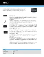
Sony Bravia KDL-32CX525, Service Manual
The Sony Bravia KDL-32CX525 is an exceptional television model that guarantees an immersive viewing experience. For easy setup and troubleshooting, a comprehensive Service Manual is available to download for free on our website, manualshive.com. Get all the necessary instructions and support to enjoy this incredible product to its fullest.
Share
Download


Reviews:
No comments
Related manuals for Bravia KDL-32CX525

VMA412
Brand: Velleman Pages: 4

FOX-122
Brand: Aaeon Pages: 37

SPLCD64G
Brand: Xantech Pages: 85

TSD-AT1513-MN
Brand: MEE Pages: 48

JDS-211
Brand: alre Pages: 16

WEGA KDE-42XS955
Brand: Sony Pages: 2

WEGA KDE-37XS955
Brand: Sony Pages: 2
VPCL224FD/B
Brand: Sony Pages: 3

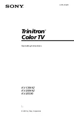
Trinitron KV-20M42
Brand: Sony Pages: 1

PlasmaPro FWD-42PV1
Brand: Sony Pages: 2

PFM-42X1S
Brand: Sony Pages: 2

NSX-46GT1
Brand: Sony Pages: 2

NSX-40GT1
Brand: Sony Pages: 2

WEGA KDE-37XS955
Brand: Sony Pages: 36

PlasmaPro FWD-42PV1
Brand: Sony Pages: 28

PFM-42X1S
Brand: Sony Pages: 24
Trinitron KV-13M42
Brand: Sony Pages: 48

Trinitron KV-20M42
Brand: Sony Pages: 55


