Siemens SIPROTEC 7SJ62, Manual
The Siemens SIPROTEC 7SJ62 is an advanced protection relay system designed to ensure optimal safety and reliable operation of electrical equipment. With our intuitive user-friendly interface, accessing the product manual is simple. Download the user manual for free from our website and maximize the potential of your SIPROTEC 7SJ62.
Share
Download


Reviews:
No comments
Related manuals for SIPROTEC 7SJ62

CLASSIC RM 2620
Brand: Dometic Pages: 54

L8DHW10
Brand: Logik Pages: 2

FT ANTIVANDAL 40m
Brand: Allmatic Pages: 8

SST-LC20
Brand: SilverStone Pages: 11

Ford 4R44E ZIP KIT
Brand: Sonnax Industries, Inc. Pages: 8

ACS 151
Brand: Bosch Pages: 20

ACS 255
Brand: Bosch Pages: 24

DSPSX000
Brand: red lion Pages: 8

MD6TU
Brand: Broan Pages: 24

Access Gate
Brand: Deer Fence Pages: 5

PCHSTAB2R
Brand: RCA Pages: 2

EduMic
Brand: Opticon Pages: 4

37x WDR
Brand: QMD Pages: 56

Z-2121 series
Brand: Zebex Pages: 48

Simple Precision SR
Brand: KAM Pages: 2

WDT-5LR-Z2
Brand: Patlite Pages: 61

CTU-M Series
Brand: Netronix Pages: 40
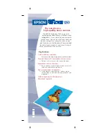
1250 - Perfection Photo Flatbed Scanner
Brand: Epson Pages: 2


