background image


Installation Instructions 

Document No. 125-1009 

February 10, 2020 


RDY2000BN BACnet Enabled 
Commercial Room Thermostat 


Item Number 125-1009, Rev. BA


Page 1 of 20 

Para accede al documento en Español, escanee el código QR que se encuentra en la parte trasera del termostato.


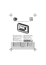
Figure 1.  RDY2000BN Thermostat. 

Product Information 

The BACnet Enabled Commercial Room Thermostat 
is designed for use with any Energy Management 
System providing BACnet MS/TP communication. 
Use Commercial Room Thermostat RDY2000BN for 
stand-alone operations. Scan QR code on 
thermostat rear housing for additional information. 

Product Number 

RDY2000BN 

Product Specifications 

System Compatibility 

Conventional 

Up to 3 Heating/3 Cooling stages 

Heat Pumps 

Up to 4 Heating/2 Cooling stages 

Electrical Characteristics


Power Supply 

24 Vac +/-20%, Class 2, 4A max.


Power Usage 

4 VA (maximum) 

Output Relay 
Ratings


Pilot duty, 1A max. per output, 4A 
max. total


MS/TP Load 

1/8 (96 K

Ω), internal network bias 

Ambient Limitations


Operating 
Temperature 

23°F to 122°F (-5°C to 50°C) 

Storage/Shipping 
Temperature 

-13°F to 158°F (-25°C to 70°C) 

Relative Humidity 

Up to 95% (non-condensing) 

Enclosure


Rating 

NEMA 1 

NOTE: 

The RDY2000BN is not battery-powered. It 
requires 24 Vac power from the HVAC 
equipment at terminals RH/RC and C. 

Caution Notations 

CAUTION: 


Equipment damage or loss of 
data may occur if you do not 
follow the procedures as 
specified. 

WARNING: 


Personal injury or loss of life 
may occur if you do not follow 
the procedures as specified. 

Required Tools 


No. 1 Phillips screwdriver 


1/8” flat-blade screwdriver 


Drill with 1/8" drill bit 

Expected Installation Time 

15 minutes 


CAUTION: 


The RDY2000BN is an advanced controller 
designed to be installed by professional 
HVAC technicians. Installation by non-
qualified personnel may result in degraded 
system efficiency, occupant discomfort, or 
equipment damage. 

Prerequisites 


WARNING: 

Turn off power to the HVAC equipment 
before attempting to remove an existing 
thermostat or install a new thermostat. 

All work must be performed in accordance with the 
applicable codes and standards. 


Energy Management System Network Plan and 
HVAC schematics are available.  


MS/TP run to thermostat using 24 AWG Low 
Capacitance 1.5 Twisted Shielded Pair cable. 
Shield and reference terminator to be earth 
grounded only at one point on network. 


HVAC equipment connections run to thermostat 
with 18 gauge thermostat wires. 


Sensor connections run to thermostat with 22 
gauge twisted pair cable or remote sensor 
wiring. Do not exceed 164 ft (50 m). 

Summary of Contents for RDY2000BN

Page 1: ...The RDY2000BN is not battery powered It requires 24 Vac power from the HVAC equipment at terminals RH RC and C Caution Notations CAUTION Equipment damage or loss of data may occur if you do not follow the procedures as specified WARNING Personal injury or loss of life may occur if you do not follow the procedures as specified Required Tools No 1 Phillips screwdriver 1 8 flat blade screwdriver Dril...

Page 2: ...wered contact by removing Jumper RC C3 and connecting dry contact wires to OUT3 and C3 See Wiring Diagrams Figure 6 Optional If using Configurable Inputs 1 to 4 or Auxiliary Outputs 1 to 3 use setup parameters P301 to P320 to set functionality 5 Attach MS TP wire to NET terminals on left of the thermostat base plate Figure 2 CAUTION To ensure signal integrity observe MS TP network wire polarity re...

Page 3: ... reminder and fault messages Service Reminders and Fault Messages Service reminders appear at the right side of the screen SERVICE UV LAMP SERVICE HUMIDIFIER SERVICE AIR FILTER They are determined by the timer set in the Installer Setup Menu and can be cleared by pressing the Settings icon and then SERVICE See Clearing Service Reminders Active fault messages appear at the left side of the home scr...

Page 4: ...Document No 125 1009 Installation Instructions February 10 2020 Page 4 of 20 Siemens Industry Inc Wiring Diagrams Figure 4 Wiring Schematic Conventional System ...

Page 5: ...nt No 125 1009 Installation Instructions February 10 2020 Siemens Industry Inc Page 5 of 20 Figure 5 Wiring Schematic Heat Pump Figure 6 Wiring Schematic Aux Output 3 Figure 7 Wiring Schematic MS TP NET Port ...

Page 6: ...s room temperature and humidity setpoints NOTE Only the setpoints in the current mode display and can be modified For instance if the thermostat is in heating mode only the heating setpoint displays and can be modified If the thermostat is in AUTO mode both the heating and cooling setpoints will be displayed and can be modified 3 Use the left and right arrows to access the different setpoints and ...

Page 7: ...nter the INSTALLER password 5 Press PASSWORD to accept the password 6 Set Parameter 211 Keypad Lockout to OFF to disable keypad lockout 7 Touch the Setpoint icon of the screen to return to the Home screen Clearing Service Reminders The thermostat displays SERVICE REQUIRED and an associated service reminder if the reminder timer Parameters 208 210 has timed out To clear these do the following 1 Tou...

Page 8: ...ng valve on heating This parameter only appears if system is heat pump P107 Scheduler Days SCHEDULER 1 2 3 7 OFF 2 1 Schedule all days with same schedule 2 One schedule for M F and another for Sat Sun 3 One schedule for M F Sat Sun scheduled individually 7 Schedule each day individually OFF Scheduler Disabled P109 Units UNITS F C F P110 Changeover AUTO CHNGE YES NO YES This parameter does not appe...

Page 9: ...re allowed above or below scheduled setpoint Unlimited This parameter does not appear if SCHEDULER OFF P206 Heat Pump Compressor Lock Out HP COMP LO OFF 15 15 F 20 20 F 25 25 F 30 30 F 35 35 F 40 40 F 45 45 F OFF Heat pump compressor will not operate below this outdoor temp forcing unit to auxiliary heat Only shown if SYS TYPE HP with AUX HEAT and there is an outdoor temp sensor Must be lower than...

Page 10: ... 45 104 104 F Normal maximum cooling setpoint Table 5 300 Series Parameters Parameter Definition Display Value Range Default Extended Definition Notes P301 Configurable Input 1 IN1 INPUT 1 1 2 3 4 5 6 7 8 9 OFF OFF 1 Indoor Temperature Remote 2 Indoor Temperature Average 3 Supply Temp 4 Return Temp 5 Outdoor Temp 6 Humidity 0 10V 7 CO2 0 10V 8 Occupancy DI 9 Fault OFF Not Used Cannot have duplicat...

Page 11: ... e g 0V 40 F Only appears if TMP IN 3 1 Must be lower than TMP 3 HI P312 Temperature Input 3 High TMP 3 HI 58 250F 50 120C 120 Calibrates thermostat to high end of temp sensor signal at 10 volts e g 10V 250 F Only appears if TMP IN 3 1 Must be higher than TMP 3 LO P313 Configurable Input 4 IN4 INPUT 4 1 2 3 4 5 6 7 8 9 OFF OFF 1 Indoor Temperature Remote 2 Indoor Temperature Average 3 Supply Temp ...

Page 12: ... an HVAC unit or zone number If any value other than is entered the sleep screen should display UNIT NUMBER in text box above room temp display P402 CO2 Set Point CO2 SET PT 500 2000 1000 Only appears if an analog input is configured as a C02 sensor P403 Pre Occupancy Purge PRE OC PRG OFF 1 2 3 OFF OFF Disabled 1 1 Hour 2 2 Hours 3 3 Hours Only show if an output is set to economizer and scheduler ...

Page 13: ...L 1 to 10 minutes 5 Time delay before next stage of cooling will be activated P502 Interstage Differential Cooling STG DIF CL 1 F 0 5 C to 10 F 5 0 C 1 F Degrees above cooling deadband before Stage Delay timer is initiated P503 Cooling Minimum Off Time M O T CL 1 to 10 minutes 5 Minimum time between compressor starts P504 Cooling Minimum On Time M R T CL 1 to 10 minutes 3 Minimum run time for any ...

Page 14: ...rate Auto value will match detected Baud Rate in systems that support and are using auto discovery leave value at default A P603 Device Instance DEV ID 0 4194303 4194303 Device Instance unsigned integer 0 4194303 In systems that support and are using auto discovery leave value at default 4194303 P604 Max Master MAX MASTER 1 127 127 Max Master P605 Serial number SER NR Display Only Display Only Dis...

Page 15: ...logged in as an Expert CAUTION P900 Series parameters are used by professional HVAC technicians during the system commissioning process Interlocks and time delays are defeated while using P900 parameters Use of these parameters by non qualified personnel may result in equipment damage Parameter Definition Display Value Range Default Extended Definition P901 Test Compressor 1 Y1 Test 1 OFF 0 ON OFF...

Page 16: ...pre purge to begin This function requires a schedule to be configured Occupancy Notification Parameters P301 P305 P309 P313 If the optional occupancy sensor is used one of these must be set to 8 P317 P318 P319 To signal an external device that the space is occupied one of these must be set to 3 P404 If the optional occupancy sensor is used P404 can be used to set a minimum run timer for any action...

Page 17: ...00 AM 1 00 PM 2 00 PM 3 00 PM 10 00 PM Table 13 Work Week Schedule with Separate Weekend Days Example 6 Periods per Day Parameter 107 3 Work Week Monday Friday Saturday Sunday Event 1 2 3 4 5 6 1 2 3 4 5 6 1 2 3 4 5 6 Mode COM ECO COM ECO COM ECO COM ECO COM ECO COM ECO COM ECO COM ECO Time 6 00 AM 11 00 AM 1 00 PM 2 00 PM 3 00 PM 10 00 PM 8 00 AM 11 00 AM 1 00 PM 2 00 PM 3 00 PM 10 00 PM 10 00 AM...

Page 18: ...on This equipment generates uses and can radiate radio frequency energy and if not installed and used in accordance with the instructions may cause harmful interference to radio communications However there is no guarantee that interference will occur in a particular installation If this equipment does cause harmful interference to radio or television reception which can be determined by turning t...

Page 19: ...fort 75 P222 Heating Setpoint Economy 62 P223 Cooling Setpoint Economy 82 P224 Heating Setpoint Protection 40 P225 Cooling Setpoint Protection 104 P301 Configurable Input 1 IN1 OFF P302 Temperature Input 1 Type 1 P303 Temperature Input 1 Low 0 F 18 0 C P304 Temperature Input 1 High 120 F 50 C P305 Configurable Input 2 IN2 OFF P306 Temperature Input 2 Type 1 P307 Temperature Input 2 Low 0 F 18 0 C ...

Page 20: ...ngeover Delay 10 P506 Cooling Deadband 1 F P507 Interstage Delay Heating 5 P508 Interstage Differential Heating Conv 1 F 0 5 C HP 2 F 1 C P509 Heating Minimum Off Time 5 P510 Heating Minimum On Time 3 10 if heat pump P511 Heating Deadband 1 F 0 5 C P601 MS TP MAC address 255 P602 Baud rate A Auto P603 Device instance 4194303 P604 Max master 127 P605 Serial number Display only P606 Max info frames ...

Reviews: