Sentry DCC02, Installation And User Manual
The Sentry DCC02 is a top-notch security camera system designed to keep your property safe. This product comes with an in-depth Installation And User Manual to guide you through the setup process. You can download the manual for free from manualshive.com, ensuring you have all the information you need at your fingertips.
Share
Download


Reviews:
No comments
Related manuals for DCC02

565
Brand: FAAC Pages: 16

2.0
Brand: Overlap Pages: 22

606S
Brand: Supeero Pages: 8

HTG 320-2
Brand: HySecurity Pages: 69

FAST KIT
Brand: CAME Pages: 32

Cardin BL Series
Brand: Riello Elettronica Pages: 20

BelFox Fabia 50
Brand: Bauer Pages: 16

Fabia50
Brand: BelFox Pages: 14

Jupiter 250
Brand: BelFox Pages: 34

Premium Slider 500
Brand: BelFox Pages: 136

47-21-11A
Brand: BelFox Pages: 160
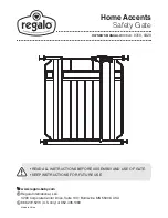
Home Accents 0310
Brand: Regalo Pages: 16

B980
Brand: Chamberlain Pages: 48

ATS 211X 1/2 HP
Brand: Chamberlain Pages: 64

B970
Brand: Chamberlain Pages: 44

ATSW
Brand: Chamberlain Pages: 80

PREMIER
Brand: Beninca Pages: 32

Essentials KEC10
Brand: Kambrook Pages: 4


