background image

V-4020C-1 INDOOR HD VIDEO 

CAMERA

Installation Guide

DESCRIPTION

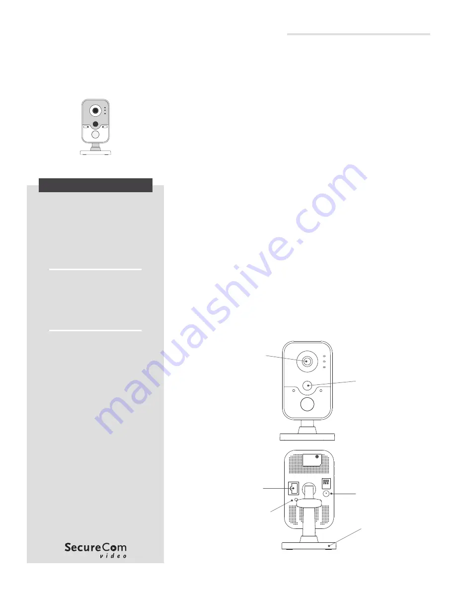
Figure 1: V-4020C-1 Indoor HD Video Camera

The V‑4020C‑1 is an indoor wired 

or wireless video camera that 

allows live view and recorded clips 

through the Virtual Keypad App™, 

as well as email motion‑triggered 

video clip notification. To activate 

the camera, you’ll need an active 

dealer account at  

dealer.securecomwireless.com.

Compatibility

• 

Any DMP system with an 

active Virtual Keypad app

• 

All SecureCom Cameras and 
NVRs

What is Included?

• 

One V‑4020C‑1 Camera

• 

Three‑axis Mounting Bracket

• 

12 VDC Power Supply

• 

Mounting Screws

1

MOUNT THE CAMERA

The V‑4020C‑1 Camera is suitable for stand, wall, and ceiling 

mounting applications. 
Refer to Figures 2 and 3 during mounting and lens adjustment.

Stand Mount

1.  Assemble the three‑axis bracket.
2.  Align the camera body to the bracket and rotate the camera 

body to connect it to the bracket.

Wall or Ceiling Mount

Ceiling mounting will be covered as an example in this section. 

However, the same steps may be referenced for wall mounting.

1.  Using the included template, mark and drill the screw holes 

for the mounting plate.

2.  Install the fixed plate with the supplied mounting screws.
3.  Fasten the mounting base to the fixed plate.
4.  Attach the camera to the bracket.

Adjust the Camera Angle

1.  Loosen the adjustment knob.
2.  Adjust the tilt direction (0° to 360°).
3.  Rotate the camera (0° to 360°) to adjust surveillance angle.
4.  To lock the camera in place, tighten the adjustment knob.

Figure 2: Indoor HD Video Camera

Lens

PIR 

Sensor

Ethernet

WPS/Reset

12 VDC 

Power

Three-Axis 

Bracket

Summary of Contents for V-4020C-1

Page 1: ...ions Refer to Figures 2 and 3 during mounting and lens adjustment Stand Mount 1 Assemble the three axis bracket 2 Align the camera body to the bracket and rotate the camera body to connect it to the bracket Wall or Ceiling Mount Ceiling mounting will be covered as an example in this section However the same steps may be referenced for wall mounting 1 Using the included template mark and drill the ...

Page 2: ...ithin 1 minute of pressing the WPS button on the WAP press and hold the WPS RESET button located on the back of the camera for three seconds See Figure 2 Once the camera and router are fully connected the WPS LED on the WAP turns on steady Connect to a Non DMP WAP with WPS 1 Plug the 12 V power supply into the camera 12 VDC power connection then connect it to a power outlet 2 Refer to the router s...

Page 3: ...d motion triggered clips only when the system is armed choose Record Motion When Armed 9 To record video clips continuously during the first minute after the system triggers an alarm select Record on Alarm 10 Press Save The device status is displayed next to the camera name Refresh the page to display the latest status When the camera is active and communicating with SecureCom video servers the st...

Page 4: ...nd Weight Camera with stand 14 1 oz Network Wireless IEEE 802 11b g n WEP64 128 bit WPA WPA2 Personal WPS Hardware Power Consumption 12 VDC Max 8 W Dimensions H x W x D Camera with stand 2 85 x 3 60 x 5 17 Compatibility Any DMP system with an active Virtual Keypad App All SecureCom Cameras and NVRs I N T R U S I O N F I R E A C C E S S N E T W O R K S 2500 North Partnership Boulevard Springfield M...

Reviews: