background image

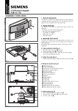
KP2000E/EM Series Style Keypad

Installation and Programming Instructions
Models KP2000EXX and KP2000EMXX

23852973

Specifications

Parameter

Specifications

Voltage 
Requirements

10-30 VDC; 12-24VAC

Keypad Current 
Requirements (Max)

VDC

VAC

10V: 85mA

12V: 150mA

30V: 115mA

24V: 200mA

Relay Contact Rating 2A @ 30VDC (Main & Aux)
REX Input

Normally Open Dry Contact

Door Position Switch 
Input

Normally Closed Dry Contact

Mechanical 
Dimensions

4.50” H x 2.75” W x 0.60” D 

Environment

Indoor or Outdoor

Temperature 
Tolerance

-31°F to 151°F (-35ºC to 66°C)

Front End Cable 
Type

Stranded and Shielded

Front End Distance 
and Wire Gauge

1000 Ft. – 18AWG; 500 Ft – 20 AWG; 250 
Ft. – 22 AWG

Firmware Version

1.0x (“1” is the major version; “0” is the 
minor version; “x” is a minor version, 
reserved for bug fixes, which is indicated 
with a letter, such as “a”.)

Keypad Operating Modes

The KP2000E/EM Series keypad has two operating modes: 
Standalone Mode and Wiegand Front End Mode. Below is a brief 
explanation of each mode. Refer to the programming section for 
details about selecting each mode.

Standalone Mode:

By default, the keypad is programmed for Standalone Mode. In this 
mode, all the users and other programming options are maintained 
within the keypad and no additional controller is required. The lock 
and all other inputs and outputs are connected directly to the keypad.

Wiegand Front End Mode:

In Wiegand Front End mode, a separate UL Listed compatible 
Wiegand Access Control panel is required. When you enter a code on 
the keypad it is then sent to the control panel as Wiegand card data, 
depending on which format you’ve programmed it for. The control 
panel maintains the users and programming options and makes all 
the access control decisions. The locking device and all inputs and 
outputs are connected to the control panel.

Mounting the Keypad

The keypad is designed to be flush mounted using a standard UL 
Listed single-gang electrical box. Mounting height can vary depending 
on requirements. An appropriate range is typically between 48 and 52 
inches on center off the floor.
For outdoor installations, use a UL Listed weatherproof back box and 
seal the wire entry locations with silicone and provide a drain hole. 
For additional protection, install the provided foam gasket between 
the keypad and the back box. In addition, use the anti-oxidant grease 
pack for the wire harness connectors.

48 - 52”

Circuit Board Diagram

1

P2

Main

Relay

Aux

Relay

1

J2

1

J3

Note: J3 is NOT USED

Summary of Contents for KP2000EM Series

Page 1: ... In this mode all the users and other programming options are maintained within the keypad and no additional controller is required The lock and all other inputs and outputs are connected directly to the keypad Wiegand Front End Mode In Wiegand Front End mode a separate UL Listed compatible Wiegand Access Control panel is required When you enter a code on the keypad it is then sent to the control ...

Page 2: ...it end All interconnecting devices ie door contacts REX locking devices alarm devices doorbell etc must be UL Listed A UL Listed access control power limited power supply capable of 4 hours standby must be used to power the keypad A minimum of three user codes must be programmed for controlling access The following Wiegand card formats were not evaluated by UL 28 bit 29 bit 30 bit 31 bit 32 bit or...

Page 3: ...l power supply Electric Strike Fail Secure V V Green V V Shunting a Normally Closed Zone 1 Connect the blue wire common to the common connection on the door position switch 2 Connect the green wire normally open to the normally closed connection on the door position switch Green Blue To Alarm Panel To Alarm Panel Wiring the REX and Door Position Switch 1 Connect the brown wire REX Input to the nor...

Page 4: ...ct Wiegand Front End Mode use the following steps 1 Enter Program Mode Press 99 master code Yellow LED Flashes Slowly 2 Select Wiegand Front End Mode press 1032 0 1 Yellow LED Flashes Slowly 3 Exit Program Mode Press Yellow LED Stops Flashing 4 Any other LED blinking sequence indicates a programming error Repeat the steps listed above to correct the problem Selecting Standalone Mode Standalone Mod...

Page 5: ...es red and green You have 15 seconds to enter the second code Two Part User Type B 10 This user type is the second half of a two part user combination After entering a Type B code you must enter a Type A code to gain access through the door Assigning Virtual Outputs to Physical Outputs Standalone Mode Only The keypad is equipped with nineteen Virtual Outputs and twelve Physical Outputs Virtual Out...

Page 6: ...h ttt and mmm Ex 12 0 0 Programming Keypad Options Default settings are in bold Command Action Keys to Enter Details Change Keypad Options 30 option setting Option Setting 0 Audio Keypress Feedback 0 Disabled 1 Enabled 1 Visual Keypress Feedback 0 Disabled 1 Enabled 2 Auto Entry 0 Disabled 1 Enabled 3 Error Lockout 0 Disabled 1 Enabled 4 User Lockout 0 Disabled 1 Enabled 5 Two Part Users 0 Disable...

Page 7: ...8191 2047 63 7 36 bit 999999 1023 N A 8 29 bit 524287 255 N A Wiegand Data When the keypad is configured in Wiegand mode the keypad data is sent as a complete Wiegand data packet as though you presented a card LED Sounder Indications Indicator Description Steady Red Door Locked Steady Green Door Unlocked timed or latched Yellow Flashing Slowly Program Mode Solid Yellow Program Error or Error Locko...

Page 8: ...ng Wiegand Front End Mode Options This section contains programming commands that apply only to Wiegand Front End Mode Enabling Disabling 8 Bit Burst Output 8 Bit Burst Mode is an alternate keypad output format This mode functions only when the keypad is programmed as a Wiegand Front End When enabled normal Wiegand operation is disabled and each key press is sent as a separate 8 bit number The cha...

Reviews: