Sargent ASSA ABLOY Harmony Series, Installation Instructions Manual
The Sargent ASSA ABLOY Harmony Series is a sleek and advanced product offering unrivaled security. Simplify your installation process with the comprehensive Installation Instructions Manual available for free download from our website. Get the manual and experience convenience and reliability with this exceptional product.
Share
Download


Reviews:
No comments
Related manuals for ASSA ABLOY Harmony Series
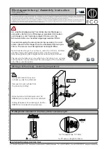
D-110
Brand: Eco Pages: 4

LE943
Brand: Abloy Pages: 16

MPC SERIES
Brand: Cobra Pages: 12

MUTO Elock MEM4400
Brand: Dormakaba Pages: 9

SmartCode Series
Brand: Kwikset Pages: 24

SBL339/SP
Brand: Securefast Pages: 2

i-Qwik PROX Series
Brand: MARKS USA Pages: 16

60117
Brand: FA Parkes Pages: 2

AD-400
Brand: Schlage Pages: 16

A Series
Brand: Schlage Pages: 32

Stock Locks C1701
Brand: COMPX Pages: 1

OU-4260
Brand: COMPX Pages: 1

ES-DLS-01
Brand: eTIGER Pages: 14

ReliTouch RT-201
Brand: Actuator Systems Pages: 88

FP6010Q-2
Brand: hentech Pages: 4

LGO
Brand: Von Duprin Pages: 2

6212WF
Brand: Von Duprin Pages: 2

FEM5700
Brand: FSH Pages: 3


