S&A CWFL-3000, User Manual
The S&A CWFL-3000 is a cutting-edge industrial chiller, designed to meet all your cooling needs. This powerful and efficient device ensures optimal performance for your machinery. Enhance your experience with this product by accessing the free user manual, available for download at manualshive.com.
Share
Download


Reviews:
No comments
Related manuals for CWFL-3000
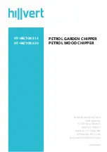
HT-HECTOR 212
Brand: hillvert Pages: 37

21A-392B401
Brand: Yard-Man Pages: 20

OMNI OWC-5 Series
Brand: Enviroheat Pages: 70

802261
Brand: Zip Pages: 16

GTS1300
Brand: Crommelins Pages: 19

M5ACV 030 CR
Brand: McQuay Pages: 99

TM 1500
Brand: Far Tools Pages: 28

BX42S
Brand: Victory Pages: 51

Touch Pilot Control Series
Brand: Carrier Pages: 36

TOUCHPILOT 30KAV
Brand: Carrier Pages: 44

FN620J
Brand: Rally Pages: 24

280 Series
Brand: Fort Pages: 36

XB590L
Brand: dixell Pages: 32

147941
Brand: Weed Eater Pages: 24

11792
Brand: Weed Eater Pages: 24

147929
Brand: Weed Eater Pages: 24

10394
Brand: Weed Eater Pages: 28

16NK
Brand: Carrier-Sanyo Pages: 44


