


Reviews:
No comments
Related manuals for CW29M066VGXXEC
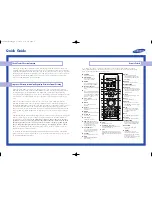
HC-P5256W
Brand: Samsung Pages: 2

CL-21K30M1
Brand: Samsung Pages: 40

LN-R1550P
Brand: Samsung Pages: 56

OCEALED39SHD21B3
Brand: Oceanic Pages: 80

DL39V200
Brand: Grandin Pages: 62

537H
Brand: Olevia Pages: 74

U42
Brand: Vantage Point Products Pages: 2

ELDFW462
Brand: Element Pages: 27

RLDED4079A-SM
Brand: RCA Pages: 41

TS3270
Brand: Magnavox Pages: 32

Easy Home HD TOPBOX
Brand: Best Buy Pages: 160

55MV346X
Brand: Magnavox Pages: 57

WinTV-soloHD
Brand: Hauppauge Pages: 2

TV-4689TFT
Brand: Premier Pages: 17

PMRS-104
Brand: INFODRAW Pages: 12
PH-50HU31
Brand: XOCECO Pages: 41

TH-43LX800Z
Brand: Panasonic Pages: 24

TX-43MX610B
Brand: Panasonic Pages: 41


