1/
3
1241045/46-
E
-01-
161006
Instruction Manual
RS Pro 35 x 77mm Defrost Thermostat, NTC, Single Output
Stock Number:
124-1045, 124-1046
• 35x77mm.
• On-Off control.
• Control output for cooling or heating.
• Single NTC probe input.
• Range -60
.0
to 150
.0
°C.
• Defrost function.
• Compressor protection settings.
• Probe failure setting, output status can be set to ON, OFF or pulse.
• Sensor input offset setting.
• “Smart Defrost” feature.
• Adjustable defrost duration and intervals.
• 6 selectable warning tones.
• High and low alarm limits, absolute or deviation.
• Temperature units °C or °F
• Digital input ;
- External alarm
- Initiate defrost
• CE marked
Please read this document carefully before using this product. The guarantee will be invalidated if the device is
damaged by not following instructions detailed in the manual. The company shall not be responsible for any damage
or losses however caused, which may be experienced as a result of the installation or use of this product.
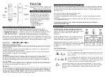
CONNECTION DIAGRAM
1241045 & 1241046
is intended for installation in control panels. Make sure that the device is used
only for intended purpose. The electrical connections must be carried out by a qualified staff
and must be according to the relevant locally applicable regulations. During an installation, all of the cables that
are connected to the device must be free of electrical power. The device must be protected against inadmissible
humidity, vibrations, severe soiling and make sure that the operation temperature is not exceeded. The cables
should not be close to the power cables or components.
SUPPLY:
NOTE:
184-253V AC
50/60Hz 4VA
Line
Neutral
230V AC
Supply
Switch
Note:
Cable size: 1,5mm²
Fuse
F 100 mA
250V AC
Fuse should
be connected
1)
Mains supply cords shall meet the requirements of
IEC 60227 or IEC 60245.
2)
In accordance with the safety regulations, the power
supply switch shall bring the identification of the
relevant instrument and it should be easily
accessible by the operator.
1
2
Holding screw
0.4-0.5Nm
Equipment is protected throughout
by DOUBLE INSULATION.
ENVIRONMENTAL CONDITIONS
Height
Max. 2000m
Ambient
/
S
torage
T
emperature
Relative
H
umidity
0 ... +50°C/-40 ... 85°C (without icing)
Protection Class
According to EN60529; Front panel : IP65, Rear panel : IP20
Do not use the device in locations subject to corrosive and flammable gasses.
Supply
V
oltage
230V AC +%10 -%20, 50/60Hz or 24V AC/DC ±%10
Power
C
onsumption
Max. 5VA
2.5mm² screw-terminal connections
±1%
4 digits, 12.5mm, 7 segment LED
Connection
Scale
Sensitivity
Accuracy
Time
A
ccuracy
Display
EMC
Safety Requirements
EN 61326-1: 201
3
EN 61010-1: 2010 (Pollution degree 2, overvoltage category II)
ELECTRICAL CHARACTERISTICS
-60.0 ... +150.0°C (-76.0 ... +302.0°F)
0.1°C (Can be selected as 0.1
ºC
or
1ºC
.)
±1°C
CONTROL
Control
T
ype
Single set-point control
On-Off control
Control
A
lgorithm
Hysteresis
Adjustable between 1 ... 20.0
°C
Life
E
xpectancy for
R
elay
OUTPUTS
HOUSING
Housing
T
ype
Suitable for flush -panel mounting
Dimensions
H35xW77xD61mm
Weight
Approx. 190g (After packing)
Enclosure
M
aterial
Self extinguishing plastics.
While cleaning the device,solvents (thinner, gasoline, acid etc.) or corrosive materials must not be used.
Relay Output
Without load 30.000.000 mechanical;
250V AC, 8A resistive load 100.000 electrical operation.
Relay : NO+NC 250V AC,8A (resistive load),
1/2HP, 0.37KW 240V AC (inductive load)
Max. humidity 80% for temperatures up to 31°C decreasing linearly to
50% relative humidity at 40°C.
DIMENSIONS
Note:
1)
Panel thickness should
be maximum 7mm.
2)
If there is no 60mm free
space at the back side of
the device,it would be
difficult to remove it from
the panel.
Flush mounting
clamp
For removing mounting clamps:
-
Push the flush-mounting
clamp in direction
1
as shown
in the figure below.Then,pull
out the clamp in direction
2
.
71,5mm
2
8
,5
m
m
Panel Cut-out
61mm 5mm
Flush mounting
clamp
Panel
Rubber
packing
2
Depth
77mm
3
5
m
m
1
EN
FOR MORE INFORMATION VISIT THIS SITE
http://www.rs-components.com/index.html
1
12
41
04
5
DIG
IT
AL
TH
ER
MO
ST
AT
Ma
de
In
T
urk
ey
1
2
3
4
5
6
7
8
9
10
SN
: X
XX
XX
XX
XX
R
S
K
E
Y
23
0V
A
C
50
/6
0H
z
N
T
C
11
12
D
IG
IN
P
CO
MP
RE
SS
OR
25
0V
8
A~
1
1241045
DIGITAL
THERMOSTAT
Made In Turkey
1
1241046
DIGITAL
THERMOSTAT
Made In Turkey
1
2
3
4
5
6
7
8
9
10
SN: XXXXXXXXX
R
S
K
E
Y
230V AC
50/60Hz
N
T
C
11 12
D
IG
I
N
P
COMPRESSOR
250V 8A~
1
2
3
4
5
6
7
8
9
10
R
S
K
E
Y
N
T
C
11 12
D
IG
I
N
P
COMPRESSOR
250V 8A~
24V AC/DC
±
10
%
50/60Hz 5VA
SN: XXXXXXXXX
124-1045
124-1046