background image

1

Montageanleitung Geräteträgersystem GTL 

Mounting instruction suspension system GTL  

Allgemeiner Hinweis
Bildliche Darstellungen können aufgrund technischer Weiterentwicklung 
von gelieferten Produkten abweichen.
Technische Änderungen und Irrtümer vorbehalten.

General information
Due to technical development, visual representations may differ from 
delivered products.
Technical modifications and errors excepted.

ROSE Systemtechnik GmbH
Erbeweg 13-15
D-32457 Porta Westfalica

Fon  +49 571 5041 0
Fax  +49 571 5041 6
E-Mail  [email protected]
Web  www.rose-pw.de

1

2

7

3

7

5

4

8

6

  1. Top mounted joint
  2. Wall hinge
  3. Intermediate joint
  4. Angle
  5. Angle GTL on GTN II
  6. Angle coupling
  7. Coupling
  8. Stand foot fixed GTL
  9. Profile GTL
10. Profile for coupling GTL
11. Profile GTN II
12. Coupling GTN II 

  1. Aufsatzgelenk
  2. Wandgelenk
  3. Zwischengelenk
  4. Winkel
  5. Winkel GTL auf GTN II
  6. Winkelkupplung
  7. Kupplung
  8. Standfuß fest GTL
  9. Profil GTL
10. Profil für Kupplung GTL
11. Profil GTN II
12. Kupplung GTN II

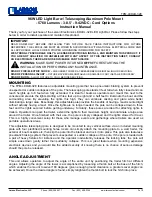
Belastungsdiagramm / 

Load diagram

[N]

1300

1200

1250 N

1100

1000

900

800

700

600

625 N

500

400

416 N

300

200

100

0,5

1

1,5

2

2,5

3

[m]

9

9

10

10

11

12

Summary of Contents for GTL

Page 1: ...tfalica Fon 49 571 5041 0 Fax 49 571 5041 6 E Mail rose rose pw de Web www rose pw de 1 2 7 3 7 5 4 8 6 1 Top mounted joint 2 Wall hinge 3 Intermediate joint 4 Angle 5 Angle GTL on GTN II 6 Angle coupling 7 Coupling 8 Stand foot fixed GTL 9 Profile GTL 10 Profile for coupling GTL 11 Profile GTN II 12 Coupling GTN II 1 Aufsatzgelenk 2 Wandgelenk 3 Zwischengelenk 4 Winkel 5 Winkel GTL auf GTN II 6 W...

Page 2: ...llen Arbeiten die persönliche Schutzausrüstung PSA Verwenden Sie geeignete Hebezeuge zur Montage und beachten Sie das hohe Eigengewicht Aufbaumöglichkeiten Assembly options Abweichende Kombinationen auf Anfrage Different combinations on request Safety instructions Use for the intended purpose The suspension system is used for the horizontal positioning of displays monitors control enclosures and o...

Page 3: ...p mounted joint Bestell Nr Order No 49 62 66 00 2 Wandgelenk Wall hinge Bestell Nr Order No 49 62 70 00 ø70 ø 1 3 160 160 70 1 3 100 110 einstellbares Drehmoment adjustable torque einstellbares Drehmoment adjustable torque ...

Page 4: ...4 3 Zwischengelenk Intermediate joint Bestell Nr Order No 49 62 67 00 4 Winkel Angle Bestell Nr Order No 49 62 71 00 einstellbares Drehmoment adjustable torque ...

Page 5: ...Winkel GTL auf GTN II Angle GTL on GTN II Bestell Nr Order No 49 62 71 47 1 2 3 6 Winkelkupplung Angle coupling Bestell Nr Order No 49 62 75 00 70 8 5 60 1 60 1 85 einstellbares Drehmoment adjustable torque ...

Page 6: ... 8 Standfuß fest GTL Stand foot fixed GTL Bestell Nr Order No 49 62 72 00 70 1 3 160 160 7 Kupplung Coupling Bestell Nr Order No 49 62 73 00 70 8 5 60 1 60 1 85 einstellbares Drehmoment adjustable torque ...

Page 7: ... 20 04 Standardlänge 3 m standard length 3 m 49 62 20 99 Variable Länge variable length 49 62 21 01 eloxal Standardlänge 0 5 m eloxal standard length 0 5 m 49 62 21 02 eloxal Standardlänge 1 m eloxal standard length 1 m 49 62 21 03 eloxal Standardlänge 2 m eloxal standard length 2 m 49 62 21 04 eloxal Standardlänge 3 m eloxal standard length 3 m 49 62 21 99 Variable Länge variable length 10 Profil...

Page 8: ...8 Material Nr 92768 Stand 05 2017 ...

Reviews: