


Industrie-Elektronik GmbH
Tel: +49/(0)7142/7776-0
Gansäcker 21
Fax: +49/(0)7142/7776-19
D-74321-Bietigheim-Bissingen (Germany)
Data subject to change
28.
7.
04
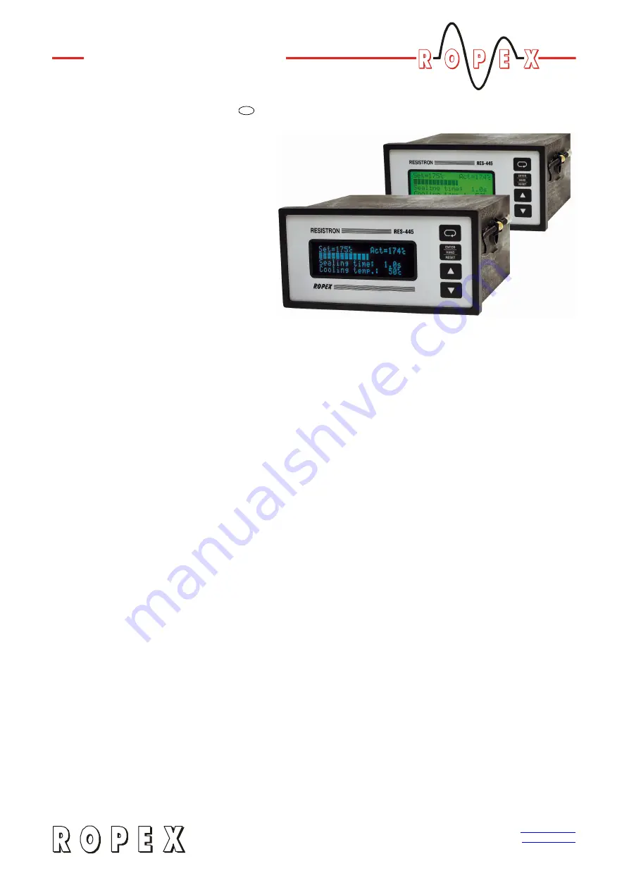
RESISTRON
RES-445
GB
Important features
• Microprocessor technology
• LC display (green), 4 lines, 20 characters, (multilingual)
Alternatively:
VF display (blue), 4 lines, 20 characters, (multilingual)
• Automatic zero calibration (AUTOCAL)
• Automatic optimization (AUTOTUNE)
• Automatic frequency adjustment
• Large current and voltage range
• Booster connection as standard
• Heatsealing band alloy and temperature range selectable
• Time control, heatsealing time and cooling time settable
• Preheating
• Configurable relay output, e.g. "end of cycle"
• Time or temperature-controlled cooling phase
• Signal output for "Temperature OK"
• 0…10VDC analog input for set point selection, electrically isolated
• 0…10VDC analog output for ACTUAL temperature, electrically isolated
• 24VDC control inputs for AUTOCAL, PREHEAT and RESET, electrically isolated
• Alarm function with fault diagnosis
Identical design to and compatible with RES-225,
Operating
Instructions


